 |
| Place of Origin: | GERMANY |
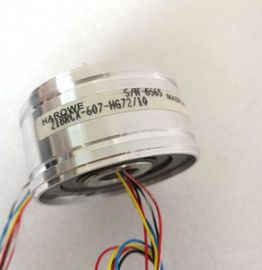
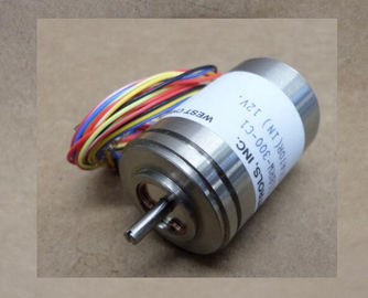
| Brand Name: | HAROWE |
| Certification: | CE |
| Model Number: | 15BRCX-500-F13P/10 |
| Minimum Order Quantity: | 1pcs |
|---|---|
| Packaging Details: | carton |
| Delivery Time: | in stock |
| Payment Terms: | T/T, Western Union, MoneyGram |
| Supply Ability: | 100pcs/week |
| HAROWE: | HAROWE | 15BRCX-500-F13P/10: | 15BRCX-500-F13P/10 |
|---|---|---|---|
| GERMANY: | GERMANY | Color: | Black |
| Material: | Iron | Temperature: | 20-90 |
| Dimension: | 90mm |
| 4.3 Address space The module can be configured differently in STEP 7; see following table. Depending on the |
|
| configuration, additional/different addresses are assigned in the process image output/input. Configuration options of DQ 16x230VAC/2A ST |
|
| You can configure the module with STEP 7 or with a GSD file. |
When you configure the module by means of the GSD file, the configurations are available
under different short designations/module names.
The following configurations are possibYou can configure the module with STEP 7 or with a GSD file.
When you configure the module by means of the GSD file, the configurations are available
under different short designations/module names.
The following configurations are possible:
Table 4- 2 Configuration options
Configuration Short designation/module
name in the GSD file
Configuration software, e.g., STEP 7
Integrated in hardware
catalog STEP 7 V13,
SP1 or higher with
HSP 0119
GSD file in
STEP 7 as of V12 or
STEP 7
as of V5.5 SP3
1 x 16-channel without value status DQ 16x230VAC/2A ST X X
1 x 16-channel with value status DQ 16x230VAC/2A ST QI X X
2 x 8-channel without value status DQ 16x230VAC/2A ST S X
(PROFINET IO only)
X
(PROFINET IO only)
2 x 8-channel with value status DQ 16x230VAC/2A ST S QI X
(PROFINET IO only)
X
(PROFINET IO only)
1 x 16-channel with value status for
module-internal Shared Output with
up to 4 submodules
DQ 16x230VAC/2A ST MSO X
(PROFINET IO only)
X
(PROFINET IO oThe value status is always activated for the following modules:
● DQ 16x230VAC/2A ST QI
● DQ 16x230VAC/2A ST S QI
● DQ 16x230VAC/2A ST MSO
An additional bit is assigned to each channel for the value status. The bit for the value status
indicates if the output value specified by the user program is actually pending at the module
terminal (0 = value is incorrect).
Address space for configuration as 16-channel DQ 16x230VAC/2A ST QI
The following figure shows the assignment of the address space for the configuration as a
16-channel module with value status. You can freely assign the start address for the module.
The addresses of the channels are derived from the start address.
The letters "a to b" are printed onto the module. "For example, AB a" stands for module start
address output byte a.For the configuration as a 2 x 8-channel module, the channels of the module are divided into
two submodules. The submodules can be assigned to different IO controllers when the
module is used in a shared device.
The number of IO controllers depends on the interface module being used. Please observe
the information in the manual for the particular interface module.
Unlike the 1 x 16-channel module configuration, each of the two submodules has a freely
assignable start address. The addresses for the respective value status of a submodule can
also be assigned by the user.If the system is in shared device mode and one of the associated IO controllers goes into
STOP or fails due to, for example, a communication failure, all submodules of the output
module follow the configured substitute value behavior (e.g. switch off).
This means that even when only one IO controller fails, the other IO controllers associated
with the shared device no longer control the assigned submodule of the output modulechannels 0 to 15 of the module are copied to multiple submodules. Channels 0 to 15 are
then available with identical values in various submodules. These submodules can be
assigned to up to four IO controllers when the module is used in a shared device:
● The IO controller to which submodule 1 is assigned has write access to outputs 0 to 15.
● The IO controllers to which submodule 2, 3, or 4 is assigned have read access to outputs
0 to 15.
The number of IO controllers depends on the interface module being used. Observe the
information in the manual for the particular interface module.
Value status (Quality Information, QI)
The meaning of the value status depends on the submodule on which it occurs.
For the first submodule (=basic submodule), the value status 0 indicates that the value is
incorrect or that the IO controller of the basic submodule is in STOP state.
For the 2nd to 4th submodule (=MSO submodule), the value status 0 indicates that the value
is incorrect or one of the following errors has occurred:
● The basic submodule is not yet configured (not ready).
● The connection between the IO controller and the basic submodule has been interrupted.
● The IO controller of the basic submodule is in STOP or POWER OFF state.he figure below show