|
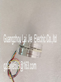
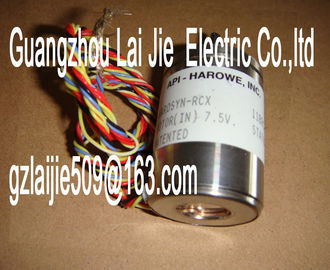
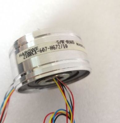
| Place of Origin: | GERMANY |
| Brand Name: | HAROWE |
| Certification: | CE |
| Model Number: | 15BRCX-500-F13PH |
| Minimum Order Quantity: | 1pcs |
|---|---|
| Packaging Details: | carton |
| Delivery Time: | in stock |
| Payment Terms: | T/T, Western Union, MoneyGram |
| Supply Ability: | 100pcs/week |
| HAROWE: | HAROWE | 15BRCX-500-F13PH: | 15BRCX-500-F13PH |
|---|---|---|---|
| GERMANY: | GERMANY | Color: | Black |
| Temperature: | 20-90 | Dimension: | 90mm |
| Wire: | Wire | Material: | Iron |
| the assignment of the address space for submodules 1 and 2 and | |
| the value status.You will find information on the module-internal shared input/shared output (MSI/MSO) | |
| the value statusThe figure below shows the assignment of the address space for submodules 3 and 4 and |
function in the function manual PROFINET with STEP 7 V13 in the section Moduleinternal
shared input/shared output (MSI/MSO).The figure below shows the LED displays (status and error displays) of the
DQ 16x230VAC/2A ST.The following tables explain the meaning of the status and error displays. Corrective
measures for diagnostics alarms can be found in the section Diagnostics alarms (Page 23)Voltage missing or too low at backplane bus ? Switch on the CPU and/or the system power
supply modules.
? Verify that the U connectors are inserted.
? Check whether too many modules are inserted.
Flashes Off
The module starts and flashes until the valid
parameter assignment is set.
---
On Off
Module parameters assigned
On Flashes
Indicates module error because supply voltage
L+ is missing
Check the supply voltage L+ at the terminals 19
and 20 or 39 and 40.
Flashes Flashes
Hardware defective Replace the moduleSupply voltage L+ too low or missing Check the supply voltage L+ at the terminals 19
and 20 or 39 and 40.
On
Supply voltage L+ is present and OKnterrupts
Digital output module DQ 16x230VAC/2A ST supports diagnostics interrupts.
Diagnostics interrupt
The module generates a diagnostic interrupt at the following event:
● No supply voltage L+
● Parameter assignment error
For more information on the error event, refer to the error OB with the "RALRM" instruction
(read additional interrupt info) and to the STEP 7 online helpA diagnostics alarm is output for each diagnostics event and the ERROR LED flashes on the
module. The diagnostics alarms can, for example, be read from the diagnostics buffer of the
CPU. You can evaluate the error codes with the user program.
If the module is operated distributed with PROFIBUS DP in an ET 200MP system, you have
the option to read out diagnostics data with the instruction RDREC or RD_REC using data
record 0 and 1. The structure of the data records is available on the in the "Manual
for interface module IM 155-5 DP ST (6E155-5BA00-0AB0)".The module cannot evaluate parameters
for the channel
Incorrect parameter assignment
Correct the parameter assignment
No load voltage 11H Supply voltage L+ of the module is
missing
Connect supply voltage L+ to module/channelHardware version E01
Firmware version V1.0.0
Product function
I&M data Yes; I&M0 to I&M3
Engineering with
STEP 7 TIA Portal can be configured/integrated
as of version
V13 SP1 / -
STEP 7 can be configured/integrated as of version V5.5 SP3 / -
PROFIBUS as of GSD version/GSD revision V1.0 / V5.1
PROFINET as of GSD version/GSD revision V2.3 / -
Operating mode
MSO Yes
Supply voltage
Rated value (DC) 24 V
Valid range, low limit (DC) 20.4 V
Valid range, high limit (DC) 28.8 V
Polarity reversal protection Yes
Power
Power consumption from the backplane bus 0.8 W
Power loss
Power loss, typ. 5 W
Digital outputs
Number of outputs 16
Sinking output Yes
Sourcing output Yes
Short-circuit protection No
Control of a digital input Yes
Switching capacity of outputs
With lamp load, maxFor signal "1" rated value 2 A
For signal "1" permitted range, min. 10 mA; 10 V
For signal "1" permitted range, max. 2 A; thermal continuous current
For signal "0" residual current, max. 0 A
Parallel switching of 2 outputs
For logic operations Yes
For increased performance No
For redundant control of a load Yes
Switching frequency
With resistive load, max. 1 Hz
With inductive load, max. 0.5 Hz
With lamp load, max. 1 Hz
Total current of outputs
Current per channel, max. 2 A; see additional description in the manual