 |
| Place of Origin: | GERMANY |
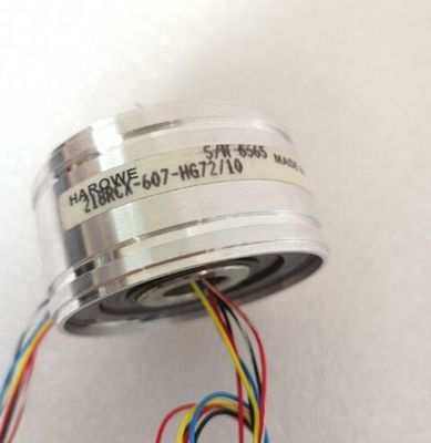
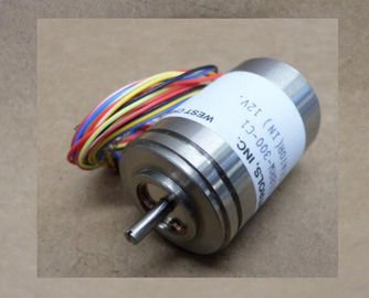
| Brand Name: | HAROWE |
| Certification: | CE |
| Model Number: | 15BRCX-500-F4 |
| Minimum Order Quantity: | 1pcs |
|---|---|
| Packaging Details: | carton |
| Delivery Time: | in stock |
| Payment Terms: | T/T, Western Union, MoneyGram |
| Supply Ability: | 100pcs/week |
| HAROWE: | HAROWE | 15BRCX-500-F4: | 15BRCX-500-F4 |
|---|---|---|---|
| GERMANY: | GERMANY | Temperature: | 20-90 |
| Wire: | Wire | Material: | Iron |
| Color: | Black | Dimension: | 90mm |
| see section Wiring (Page 19). You can find the total current of the outputs for each channel | |
| or for each module in the technical specifications.The dimensional drawing of the module on the mounting rail, as well as a dimensiona | |
| drawing with open front cover, are provided in the appendix. Always observe the specified dimensions for installations in cabinets, control rooms, etcThe data records of the module have an |
identical structure, regardless of whether you
configure the module with PROFIBUS DP or PROFINET IO.
Dependencies for configuration with GSD file
When a GSD file is used to configure a module, dependencies can arise when "assigning the
parameters".
There are no dependencies for this module. You can assign the individual parameters in any
combination.
Parameter assignment in the user program
You have the option to reconfigure the module in RUN (e.g. the response of selected
channels to the CPU-STOP state can be changed in RUN without having an effect on the
other channels).
Parameter assignment in RUN
The WRREC instruction is used to transfer the parameters to the module using data sets 64
to 71. The parameters set in STEP 7 do not change in the CPU, which means the
parameters set in STEP 7 are still valid after a restart.
The parameters are only checked for plausibility by the module after the transferThe module ignores errors that occurred during the transfer of parameters with the WRREC
instruction and continues operation with the previous parameter assignment. However, a
corresponding error code is written to the STATUS output parameter.
The description of the WRREC instruction and the error codes is available in the STEP 7
online help.The WRREC instruction is used to transfer the parameters to the module using data sets 64
to 71. The parameters set in STEP 7 do not change in the CPU, which means the
parameters set in STEP 7 are still valid after a restart.
The parameters are only checked for plausibility by the module after the transfer.The channel parameters of the module are included in data sets 64 to 71 and are assigned
as follows:
● Data set 64 for channel 0 (PWM operating mode possible)
● Data record 65 for channel 1
● Data set 66 for channel 2
● Data set 67 for channel 3
● Data set 68 for channel 4 (PWM operating mode possible)
● Data set 69 for channel 5
● Data set 70 for channel 6
● Data set 71 for channel 7The figure below shows the structure of data set 64 for channel 0 as an example. The
structure is identical for channels 1 to 7. The values in byte 0 and byte 1 are fixed and may
not be changed.
Enable a parameter by setting the corresponding bit to "1".
The figure below shows the structure of data set 64 for channel 0 as an example. The
structure is identical for channels 1 to 7. The values in byte 0 and byte 1 are fixed and may
not be changed.
Enable a parameter by setting the corresponding bit to "1".
This manual contains notices you have to