 |
| Place of Origin: | GERMANY |
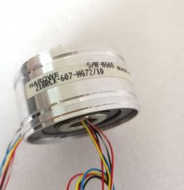
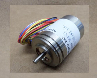
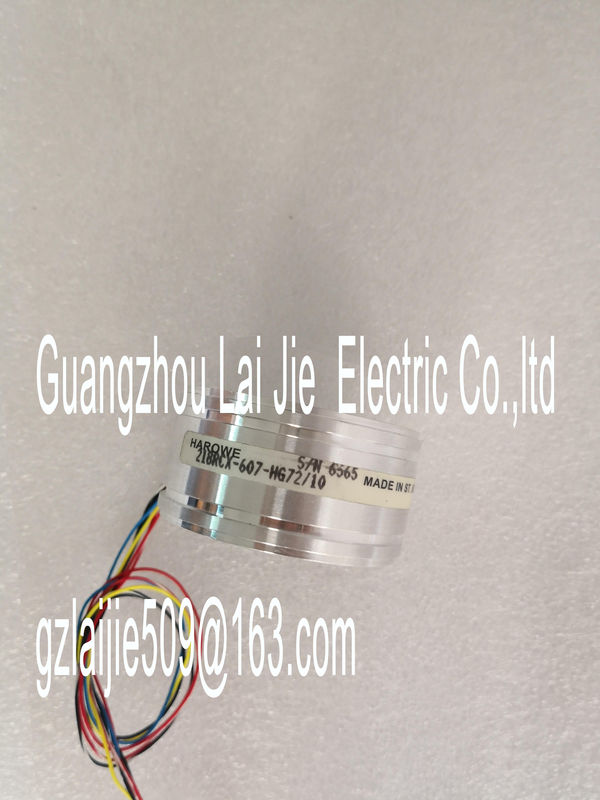
| Brand Name: | HAROWE |
| Certification: | CE |
| Model Number: | 15BRCX-500-G44 |
| Minimum Order Quantity: | 1pcs |
|---|---|
| Packaging Details: | carton |
| Delivery Time: | in stock |
| Payment Terms: | T/T, Western Union, MoneyGram |
| Supply Ability: | 100pcs/week |
| HAROWE: | HAROWE | Material: | Iron |
|---|---|---|---|
| Color: | Black | Temperature: | 20-90 |
| Dimension: | 90mm | Germany: | Germany |
| Wire: | Wire | 15BRCX-500-G44: | 15BRCX-500-G44 |
| 15BRCX-500-G44module ● Program download to CPU |
|
| Operating mode switchover RUN/STOP | |
| Localization of the CPU by means of LED flashing |
Reading out CPU error information
● Reading the CPU diagnostic buffer
● Reset to factory settings
● Updating the firmware of the CPU and connected modules
You can find the SIMATIC Automation Tool on the With PRONETA (PROFINET network analysis), you analyze the PROFINET
network during commissioning. PRONETA features two core functions:
● The topology overview independently scans PROFINET and all connected components.
● The IO check is a fast test of the wiring and the module configuration of a system.
You can find PRONETA on the The module has the following technical properties:
● Digital inputs
– 16 digital inputs; electrically isolated in groups of 16
– Rated input voltage 24 VDC
– Suitable for switches and 2-/3-/4-wire proximity switches
● Digital outputs
– 16 digital outputs, electrically isolated in groups of 8
– Rated output voltage 24 VDC
– Rated output current 0.5 A per channel
– Suitable for solenoid valves, DC contactors, and indicator lights
The module supports the following functions:
Table 2- 1 Version dependencies of the module functionsFirmware update V1.0.0 or higher V13 or higher X
Identification data I&M0 to I&M3 V1.0.0 or higher V13 or higher X
Module-internal Shared Input (MSI)
/ Shared Output (MSO)
V1.0.0 or higher V13 Update 3 or higher
(PROFINET IO only)
X
(PROFINET IO only)
Configurable submodules / submodules
for Shared Device
V1.0.0 or higher V13 Update 3 or higher
(PROFINET IO only)
X
(PROFINET IO only)
You can configure the module with STEP 7 (TIA Portal) and with a GSD file.
Accessories
The following components are supplied with the module and can also be ordered separately
as spare parts:
● Front connector (push-in terminals) including cable tie
● Labeling strips
● U connector
● Universal front door
You can find additional information on accessories in the S7-1500/ET 200MP This section contains the block diagram of the module and outlines various wiring options.
You can find information on wiring the front connector, creating a cable shield, etc. in the
Wiring section of the S7-1500/ET 200MPThe figure below shows you how to connect the module and the assignment of the channels
to the addresses (input byte a and b, output byte c and d).Backplane bus interface CHx Channel or channel status LED (green)
xL+ Supply voltage 24 V DC RUN Status display LED (green)
xM Ground ERROR Error display LED (red)
PWR POWER supply voltage LED (green)
Figure 3-1 Block diagram and terminal assignmentThe module can be configured in various ways in STEP 7. Depending on the configuration,
additional/different addresses are assigned in the process image input/output.
Configuration options of DI 16x24VDC/DQ 16x24VDC/0.5A BA
You can configure the module with STEP 7 (TIA Portal) or with a GSD file.
When you configure the module by means of the GSD file, the configurations are available
under different abbreviations/module names.