|
| Place of Origin: | GERMANY |
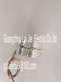
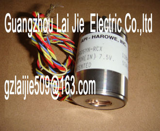
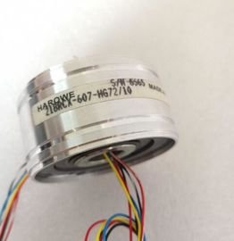
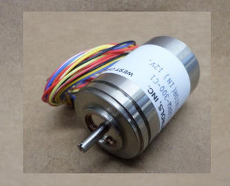
| Brand Name: | HAROWE |
| Certification: | CE |
| Model Number: | 15BRCX-500-G4B |
| Minimum Order Quantity: | 1pcs |
|---|---|
| Packaging Details: | carton |
| Delivery Time: | in stock |
| Payment Terms: | T/T, Western Union, MoneyGram |
| Supply Ability: | 100pcs/week |
| HAROWE: | HAROWE | 15BRCX-500-G4B: | 15BRCX-500-G4B |
|---|---|---|---|
| Material: | Iron | Color: | Black |
| Temperature: | 20-90 | Dimension: | 90mm |
| Wire: | Wire | Germany: | Germany |
| The following configurations are possible1 x 32-channel without value status (1 x 16 digital inputs and 1 x 16 digital outputs) |
|
| V13 or higher X 4 x 8-channel without value status (2 x 8 |
|
| DI 16x24VDC/ DQ 16x24VDC/0.5 BA |
digital inputs and 2 x 8 digital outputs)
DI 16x24VDC/
DQ 16x24VDC/0.5 BA S
V13 Update 3 or higher
(PROFINET IO only)
X
(PROFINET IO only)
1 x 32-channel with value status for up
to 4 submodules
(each 1 x 16 channels for moduleinternal
Shared Input or Shared Output)
DI 16x24VDC/
DQ 16x24VDC/0.5 BA MSI
or MSO
V13 Update 3 or higher
(PROFINET IO only)
X
(PROFINET IO only)The figure below shows the address space assignment for configuration as a 1 x 32-channel
module (16 digital inputs / 16 digital outputs). You can freely assign the start address for the
module. The addresses of the channels are derived from the start address.
The letters "a to d" are printed on the module- "EB a", for example, stands for module start
address input byte a.
For the configuration as a 4 x 8-channel module, the channels of the module are divided into
multiple submodules. The submodules can be assigned to different IO controllers when the
module is used in a shared device.
The number of usable IO controllers depends on the interface module used. Please observe
the information in the manual for the particular interface module.
Unlike the 1 x 32-channel module configuration, each of the four submodules has a freely
assignable start address.For configuration as a 1 x 32-channel module (module-internal Shared Input, MSI/Shared
Output, MSO), the channels for inputs or outputs 0 to 15 of the module are copied to multiple
submodules. Each of the channels 0 to 15 are then available with identical values in various
submodules. These submodules can be assigned to up to four IO controllers when the
module is used in a Shared Device:
● The IO controller to which submodule 1 is assigned has write access to output channels 0
to 15 and read access to the input channels 0 to 15.
● The IO controllers to which submodule 2, 3 or 4 is assigned have read access to the input
channels or output channels 0 to 15.
The number of usable IO controllers depends on the interface module used. Please observe
the information in the manual for the particular interface module.
Value status (Quality Information, QI) for inputs
The meaning of the value status depends on the submodule involved.
For the 1st submodule (=basic submodule), the value status is not relevant.
For the 2nd to 4th submodule (=MSI submodule), the value status 0 indicates that the value
is incorrect or the basic submodule has not yet been configured (not ready).
Value status (Quality Information, QI) for outputs
The meaning of the value status depends on the submodule involved.
For the 1st submodule (=basic submodule), the value status 1 indicates that the output value
specified by the user program is actually output at the module terminal.
Possible causes for value status = 0:
● Value is incorrect, for example, because the supply voltage is missing.
● IO controller of the basic submodule is in STOP mode.
For the 2nd to 4th submodule (=MSO submodule), the value status 1 indicates that the
output value specified by the user program is actually output at the module terminal.
Possible causes for value status = 0:
● Value is incorrect, for example, because the supply voltage is missing.
● IO controller of the basic submodule is in STOP mode.
● The basic submodule is not yet configuredThe figure below shows the assignment of the address space with submodule 1 and the
value status.The figure below shows the assignment of the address space with submodule 2 and the
value status.The figure below shows the assignment of the address space with submodule 3 and the
value status.The figure below shows the assignment of the address space with submodule 4 and the
value status.You can find information on the module-internal shared input/shared output (MSI/MSO)
function in the section Module-internal shared input/shared output (MSI/MSO) of the function
manual PROFINET with STEP 7 V13 The module has no selectable diagnostics. Diagnostics alarms, for example, cannot be
output with STEP 7 (TIA Portal).
5.1 Status and error displays
LED displays
The figure below shows the LED displays (status and error displays) of the DI
16x24VDC/DQ 16x24VDC/0.5A BA.Voltage missing or too low at backplane bus. • Switch on the CPU and/or the system power