 |
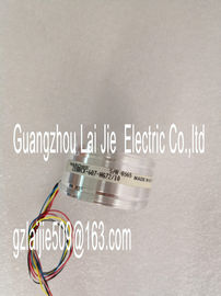
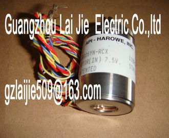
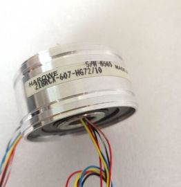
| Place of Origin: | GERMANY |
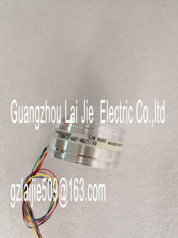
| Brand Name: | HAROWE |
| Certification: | CE |
| Model Number: | 15BRCX-500-J12 |
| Minimum Order Quantity: | 1pcs |
|---|---|
| Packaging Details: | carton |
| Delivery Time: | in stock |
| Payment Terms: | T/T, MoneyGram, Western Union |
| Supply Ability: | 100pcs/week |
| HAROWE: | HAROWE | 15BRCX-500-J12: | 15BRCX-500-J12 |
|---|---|---|---|
| GERMANY: | GERMANY | Temperature: | 20-90 |
| Color: | Black | Dimension: | 90mm |
| Wire: | Wire | Material: | Iron |
![]()
![]()
![]()
![]()
| pply modules. • Verify that the U connectors are inserted. |
|
| Check to see if too many modules are inserted.Supply voltage L+ too low or missing Check supply voltage L+. | |
| On Supply voltage L+ is present and OK.Product type designation DI 16x24VDC / DQ16x24VDC/0.5A BA |
Hardware functional status FS01
Firmware version V1.0.0
• FW update possible Yes
Product function
I&M data Yes; I&M0 to I&M3
Engineering with
STEP 7 TIA Portal can be configured/integrated
as of version
V13 / V13
STEP 7 can be configured/integrated as of version V5.5 SP3 / -
PROFIBUS as of GSD version/GSD revision V1.0 / V5.1
PROFINET as of GSD version/GSD revision V2.3 / -
Operating mode
DI Yes
Counters No
DQ Yes
DQ with energy-saving function No
PWM No
Oversampling No
MSI Yes
MSO Yes
Supply voltage
Rated value (DC) 24 V
Valid range, low limit (DC) 20.4 V
Valid range, high limit (DC) 28.8 V
Reverse polarity protection Yes; with internal protection with 7 A per group
Input current
Current consumption, max. 30 mA
Output voltage
Rated value (DC) 24 V
Power
Power consumption from the backplane bus 1.1 W
Power loss
Power loss, typ. 3.45 WNumber of outputs 16
Sourcing output Yes
Short-circuit protection Yes
• Response threshold, typ. 1 A
Limitation of inductive shutdown voltage to L+ (-53 V)
Activation of a digital input Yes
Switching capacity of the outputs
With resistive load, max. 0.5 A
With lamp load, max. 5 W
Load resistance range
Low limit 48 Ω
High limit 12 kΩ
Output voltage
for signal "1", minOutput current
For signal "1" rated value 0.5 A
For signal "1" permitted range, max. 0.5 A
For signal "0" residual current, max. 0.5 mA
Output delay with resistive load
"0" to "1", max. 100 µs
"1" to "0", max. 500 µs
Parallel connection of two outputs
For logical operations Yes
For increased performance No
For redundant activation of a load Yes
Switching frequency
With resistive load, max. 100 Hz
With inductive load, max. 0.5 Hz
With lamp load, max. 10 Hz
Total current of the outputs
Current per channel, max. 0.5 A; see additional description in the manual
Current per group, max. 4 A; see additional description in the manual
Current per module, max. 8 A; see additional description in the manual
Cable length
shielded, max. 1000 m
unshielded, max. 600 m
Encoders
Connectable encoders
2-wire sensor Yes
• Permitted quiescent current (2-wire sensor),
max.
1.5 mA
Isochronous mode
Isochronous mode (application synchronized up to
terminal)
No
Interrupts/diagnostics/status information
Diagnostics function No
Substitute values can be applied No
Interrupts
Diagnostics interrupt No
Hardware interrupt No
Diagnostics alarms
Monitoring of supply voltage No
Wire break No
Short-circuit No
Group errorRUN LED Yes; green LED
ERROR LED Yes; red LED
Monitoring of supply voltage (PWR LED) Yes; green LED
Channel status display Yes; green LED