 |
| Place of Origin: | GERMANY |
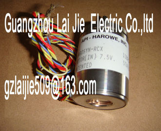
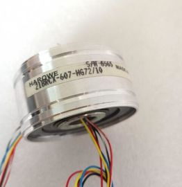
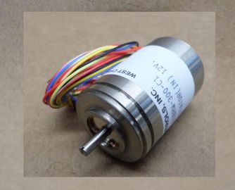
| Brand Name: | HAROWE |
| Certification: | CE |
| Model Number: | 15BRCX-500-EJ4 |
| Minimum Order Quantity: | 1pcs |
|---|---|
| Packaging Details: | carton |
| Delivery Time: | in stock |
| Payment Terms: | T/T, Western Union, MoneyGram |
| Supply Ability: | 100pcs/week |
| HAROWE: | HAROWE | 15BRCX-500-EJ4: | 15BRCX-500-EJ4 |
|---|---|---|---|
| GERMANY: | GERMANY | Temperature: | 20-90 |
| Color: | Black | Dimension: | 90mm |
| Wire: | Wire |
| Measuring type resistance thermometers (RTD) adjustable for channel 0, 2, 4 and 6 | |
| Thermocouple (TC) measurement type can be set per channel | |
| Resolution 16 bits including sign |
Configurable diagnostics (per channel)
● Hardware interrupt on limit violation can be set per channel (two low and two high limits
per channel)
The module supports the following functions:
Table 2- 1 Version dependencies of the module functionFirmware update V1.0.0 or higher V12 or higher X
Identification data I&M0 to I&M3 V1.0.0 or higher V12 or higher X
Parameter assignment in RUN V1.0.0 or higher V12 or higher X
Isochronous mode V1.0.0 or higher V12 or higher ---
Calibration in runtime V1.0.0 or higher V12 or higher X
Module-internal Shared Input (MSI) V2.0.0 or higher V13 Update 3 or
higher
(PROFINET IO
only)
X
(PROFINET IO only)
Configurable submodules / submodules for
Shared Device
V2.0.0 or higher V13 Update 3 or
higher
(PROFINET IO
only)
X
(PROFINET IO only)
Configurable after interface module
IM 155-5 DP ST
V2.0.0 or higher V13 or higher X
You can configure the module with STEP 7 (TIA Portal) and with a GSD file.The following table shows the compatibility of the modules and the dependencies between
hardware functional status (FS) and firmware version (FW) used:
Hardware functional status Firmware version Note
FS01 V1.0.0 to V2.0.x Upgrade to downgrade possible between
V1.0.0 and V2.0.x FS02 V1.0.0 to V2.0.x
FS03 V2.1.0 to V2.1.x Upgrade to downgrade possible between
V2.1.0 and V2.1.x
FS04 V2.2.0 or higher Upgrade and downgrade possible between
V2.2.0 and higher
Accessories
The following accessories are supplied with the module and can also be ordered separately
as spare parts:
● Shield bracket
● Shield terminal
● Power supply element
● Labeling strips
● U connector
● Universal front door
Other components
The following component can be ordered separately:
Front connectors, including potential jumpers and cable ties
You can find additional information on accessories in the system manual S7-1500/ET 200MP This section contains the block diagram of the module and outlines various connection
options.
You can find information on wiring the front connector, creating a cable shield, etc. in the
Wiring section of the system manual S7-1500/ET 200MP record in the section Structure of a data record for dynamic reference temperature
(Page 65).
Note
• You may use and combine the different wiring options for all channels.
• Do not insert the potential jumpers supplied with the front connector.Meaning of the abbreviations
used in the following figures:
Un+/Un- Voltage input channel n (voltage only)
Mn+/Mn- Measuring input channel n
In+/In- Current input channel n (current only)
Ic n+/Ic n- Current output for RTD, channel n
UVn Supply voltage at channel n for 2-wire transmitters (2WMT)
Comp+/Comp- Compensation input
IComp+/IComp- Current output for compensation
L+ Connection for supply voltage
M Ground connection
MANA Reference potential of the analog circuitThe power supply element is plugged onto the front connector for powering the analog
module. Wire the supply voltage to terminals 41 (L+) and 44 (M). You can use terminals 42
(L+) and 43 (M) to loop the potential to the next module.Analog-to-digital converter (ADC) CHx Channel or 9 x channel status (green/red)
② Backplane bus interface RUN Status display LED (green)
③ Supply voltage via power supply element ERROR Error display LED (red)
④ Equipotential bonding cable (optional) PWR LED for power supply (green)
Figure 3-2 Block diagram and pin assignment for voltage measurementWiring 4-wire transmitter CHx Channel or 9 x channel status (green/red)
② Analog-to-digital converter (ADC) RUN Status display LED (green)
③ Backplane bus interface ERROR Error display LED (red)
④ Supply voltage via power supply element PWR LED for power supply (green)
⑤ Equipotential bonding cable (optional)
Figure 3-3 Block diagram and pin assignment for current measurementWiring 2-wire transmitter CHx Channel or 9 x channel status (green/red)
② Analog-to-digital converter (ADC) RUN Status display LED (green)
③ Backplane bus interface ERROR Error display LED (red)
④ Supply voltage via power supply element PWR LED for power supply (green)
⑤ Equipotential bonding cable (optional)
Figure 3-4 Block diagram and pin assignment for current measurement① 4-wire connection CHx Channel or 9 x channel status (green/red)
② 3-wire connection RUN Status display LED (green)