 |
| Place of Origin: | GERMANY |
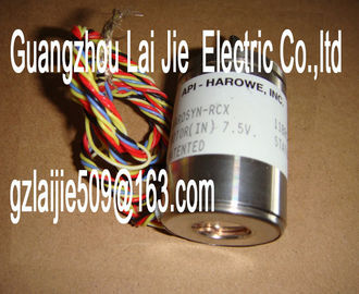
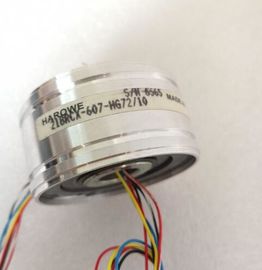
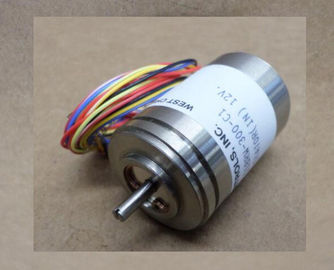
| Brand Name: | HAROWE |
| Certification: | CE |
| Model Number: | 15BRCX-600-J43 |
| Minimum Order Quantity: | 1pcs |
|---|---|
| Packaging Details: | carton |
| Delivery Time: | in stock |
| Payment Terms: | T/T, Western Union, MoneyGram |
| Supply Ability: | 100pcs/week |
| HAROWE: | HAROWE | 15BRCX-600-J43: | 15BRCX-600-J43 |
|---|---|---|---|
| GERMANY: | GERMANY | Material: | Iron |
| Color: | Black | Temperature: | 20-90 |
| Wire: | Wire | Dimension: | 90mm |
| Voltage missing or too low at backplane bus. • Switch on the CPU and/or the system power supply modules. |
|
| Verify that the U connectors are inserted. • Check to see if too many modules are inserted. |
|
| Flashes Off The module starts and flashes until the valid |
parameter assignment is set.
---
On Off
Module is configured.
On Flashes
Indicates module errors (at least one error at
one channel, e.g., wire break).
Evaluate the diagnostics data and eliminate the
error (e.g., wire break).
Flashes Flashes
Hardware defective. Replace the module.
PWR LED
Table 5- 2 PWR status display
LED PWR Meaning Remedy
Off
Supply voltage L+ to module too low or missing Check supply voltage L+.
On
Supply voltage L+ is present and OK.Channel disabled ---
On
Channel configured and OK. ---
On
Channel is configured (channel error pending).
Diagnostic alarm: e.g. wire break
Check the wiring.
Disable diagnostics.You can find detailed information on the event in the error organization block with the
"RALRM" instruction (read additional interrupt info) and in the STEP 7 online help.
Diagnostic interrupt
The module generates a diagnostic interrupt at the following events:
● Missing supply voltage L+
● Wire break
● Overflow
● Underflow
● Common mode error
● Reference channel error
● Parameter assignment error
Hardware interrupt
The module generates a hardware interrupt at the following events:
● Low limit violated 1
● High limit violated 1
● Low limit violated 2
● Above high limit 2
The module channel that triggered the hardware interrupt is entered in the start information
of the organization block. The diagram below shows the assignment to the bits of double If the two high limits 1 and 2 are reached at the same time, the module always signals the
hardware interrupt for high limit 1 first. The configured value for high limit 2 is irrelevant. After
processing the hardware interrupt for high limit 1, the module triggers the hardware interrupt
for high limit 2.
The module has the same reaction when the low limits are reached at the same time. If the
two low limits 1 and 2 are reached at the same time, the module always signals the
hardware interrupt for low limit 1 first. After processing the hardware interrupt for low limit 1,
the module triggers the hardware interrupt for low limit 2.(User Structure Identifier)
W#16#0001 Additional interrupt info for hardware interrupts
of the I/O module
2
The channel that triggered the hardware interrupt follows.
Channel B#16#00 to B#16#n Number of the event-triggering channel (n =
number of module channels -1)
1
The event that triggered the hardware interrupt follows.
Event B#16#03 Low limit violated 1 1
B#16#04 High limit violated 1
B#16#05 Low limit violated 2
B#16#06 Violation of high limit 2A diagnostics alarm is generated and the ERROR LED flashes on the module for each
diagnostics event. The diagnostics alarms can be read out in the diagnostics buffer of the
CPU, for example. You can evaluate the error codes with the user program.
If the module is operated distributed with PROFIBUS DP in an ET 200MP system, you have
the option to read out diagnostics data with the instruction RDREC or RD_REC using data
record 0 and 1. The structure of the data records is available on the in the "Manual
for interface module IM 155-5 DP ST (6ES7155-5BA00-0AB0)Wire break 6H Impedance of encoder circuit too high Use a different encoder type or modify the
wiring, for example, using cables with
larger cross-section
Wire break between the module and sensor
Connect the cable
Channel not connected (open) • Disable diagnostics
• Connect the channel
Overflow 7H Measuring range violated Check the measuring range
Underflow 8H Measuring range violated Check the measuring range