 |
| Place of Origin: | GERMANY |
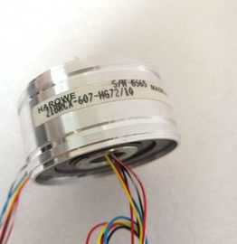
| Brand Name: | HAROWE |
| Certification: | CE |
| Model Number: | 15BRCX-602-B10E |
| Minimum Order Quantity: | 1pcs |
|---|---|
| Packaging Details: | carton |
| Delivery Time: | in stock |
| Payment Terms: | T/T, Western Union, MoneyGram |
| Supply Ability: | 100pcs/week |
| HAROWE: | HAROWE | 15BRCX-602-B10E: | 15BRCX-602-B10E |
|---|---|---|---|
| GERMANY: | GERMANY | COLOR: | BLACK |
| Temperature: | 20-90 | Dimension: | 90mm |
| Material: | Iron |
| When configuring the module with a GSD file, remember that the settings of some parameters are dependent on each other. The parameters are only checked for plausibility |
|
| by the module after the transfer to the module. The following table lists the parameters that depend on one another. |
|
| Table B- 1 Dependencies of parameters for configuration with GSD file Device-specific parameters (GSD file) Dependent parameters |
Current limit for wire break Only for measuring type current with measuring range 4 mA to 20 mA.
Wire break Only for measuring type resistance, thermal resistor RTD, thermocouple
TC, voltage with measuring range 1V to 5 V and current with measuring
range 4 mA to 20 mA.
Common mode error Only for measuring type voltage, current and thermocouple TC.
Reference channel error Only for measuring type thermocouple TC.
Measuring type resistance (4-wire connection,
3-wire connection)
Only for measuring range 150 Ω, 300 Ω, 600 Ω and 6000 Ω.
Measuring type resistance (4-wire connection,
3-wire connection, 2-wire connection) Configurable for even channels (0, 2, 4 and 6) only.
Measuring type The following odd channel (1, 3, 5, 7) must be deactivated. thermal resistor RTD (4-wire
connection, 3-wire connection)
Hardware interrupt limits Only if hardware interrupts are enabled.
Fixed reference temperature Only if the value Fixed reference temperature is configured at parameter
Reference junction for TC.
Temperature unit Kelvin (K) Only for measuring type thermal resistor RTD and for thermocouple TC.
Parameter assignment in the user program
The module parameters can be assigned in RUN (for example, measuring ranges of
selected channels can be edited in RUN without having an effect on the other channels).
Parameter assignment in RUN
Instruction WRREC is used to transfer the parameters by means of data records 0 to 7 and
8. The parameters set in STEP 7 do not change in the CPU, which means the parameters
set in STEP 7 are still valid after a restart.
The parameters are only checked for plausibility by the module after the transfer to the
module.The module ignores errors that occurred during the transfer of parameters with the WRREC
instruction and continues operation with the previous parameter assignment. However, a
corresponding error code is written to the STATUS output parameter.
The description of the WRREC instruction and the error codes is available in the STEP 7
online help.
Operation of the module behind a PROFIBUS DP interface module
If the module is operated behind a PROFIBUS DP interface module, the parameter data
records 0 and 1 are not read back. You obtain the diagnostics data records 0 and 1 with the
read back parameter data records 0 and 1. You can find additional information in the
Interrupts section of the manual for the PROFIBUS DP interface module on the The parameters in data records 0 to 7 and in data record 8 are available for 1x 8-channel
configuration and are assigned as follows:
● Data record 0 for channel 0
● Data record 1 for channel 1