|
| Place of Origin: | GERMANY |
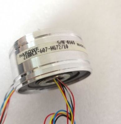
| Brand Name: | HAROWE |
| Certification: | CE |
| Model Number: | 15BRCX-602-B21/10 |
| Minimum Order Quantity: | 1pcs |
|---|---|
| Packaging Details: | carton |
| Delivery Time: | in stock |
| Payment Terms: | T/T, Western Union, MoneyGram |
| Supply Ability: | 100pcs/week |
| HAROWE: | HAROWE | 15BRCX-602-B21/10: | 15BRCX-602-B21/10 |
|---|---|---|---|
| GERMANY: | GERMANY | COLOR: | BLACK |
| TEMPERATURE: | 20-90 | WIRE: | WIRE |
| Dimension: | 90mm |
| Data record 6 for channel 6 ● Data record 7 for channel 7 |
|
| Data record 8 for the reference channel (COMP) | |
| For configuration 8 x 1-channel, the module has 8 submodules with one channel each and |
one submodule for the reference channel. The parameters for the channel are available in
data record 0 and are assigned as follows:
● Data record 0 for channel 0 (submodule 1)
● Data record 0 for channel 1 (submodule 2)
● …
● Data record 0 for channel 6 (submodule 7)
● Data record 0 for channel 7 (submodule 8)
● Data record 0 for the reference channel (COMP) (submodule 9)
Address the respective submodule for data record transfer.The figure below shows the structure of data record 0 for channel 0 as an example. The
structure is identical for channels 1 to 7. The values in byte 0 and byte 1 are fixed and may
not be changed.
Enable a parameter by setting the corresponding bit to "1"The reference channel compensates the measured value for channels 0 to 7. The figure
below shows the structure of data record 8. Enable a parameter by setting the corresponding
bit to "1".The following table lists all measurement types of the analog input module along with their
codes. Enter these codes at byte 2 of the data record for the corresponding channel (see the
figure Structure of data record 0: Bytes 7 to 27).
Table B- 2 Code for the measurement typonly possible for channels 0, 2, 4 and 6
**) only for the following measuring ranges: 150 Ω, 300 Ω, 600 Ω, 6 kΩ
***) only for measuring range PTC
Special feature for configuration
If you configure one of the following measuring types at one of the channels 0, 2, 4 and 6:
● Resistance, 4-wire connection
● Resistance, 3-wire connection
● Resistance, 2-wire connection
● Thermal resistor linear, 4-wire connection
● Thermal resistor linear, 3-wire connection
then one of the following channels must be disabled.
ExampleThe following table lists all measuring ranges of the analog input module along with their
codes. Enter these codes accordingly at byte 3 of the data record for the corresponding
channel (see the figure Structure of data record 0: Bytes 7 to 27).The following table lists all measuring ranges along with their codes for the reference
channel (COMP). Enter these codes in byte 3 of data record 8 (see figure Structure of data
record 8, reference channel of the module: Bytes 0 to 27).
Table B- 4 Code for the measuring range, reference channel (COMP)perature coefficients
The following table lists all temperature coefficients along with their codes for temperature
measurements with the thermal resistors. You need to enter these codes in
● byte 4 of data record 8 (see figure, Structure of data record 8, reference channel of the
module: bytes 0 to 27) and
● byte 4 of data records 0, 2, 4, 6 and 8 (see figure, Structure of data record 0: Bytes 0 to 6)
Table B- 5 Codes for temperature coefficient
The values that you can set for fixed reference temperatures must be in the valid range of
values. The resolution is a tenth of a degree.
Table B- 6 Valid values for fixed reference temperatures
Temperature unit Decimal Hexadecimal
Celsius (default) -1450 to 15The values that you can set for hardware interrupts (high/low limit) must not violate the
over/underrange of the respective rated measuring range.
The following tables list the valid hardware interrupt limits. The limits depend on the selected
measurement type and measuring range.
Table B- 7 Voltage limits
The WRREC instruction is used to transfer the reference junction temperature via data
record 192 to data record 199 to the module.
The description of the WRREC instruction can be found in the online help from STEP 7.