|
| Place of Origin: | GERMANY |
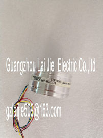
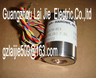
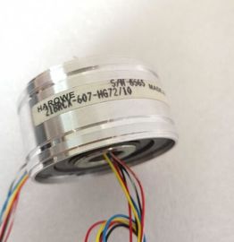
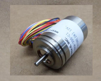
| Brand Name: | HAROWE |
| Certification: | CE |
| Model Number: | 15BRCX-602-BA47/10 |
| Minimum Order Quantity: | 1pcs |
|---|---|
| Packaging Details: | carton |
| Delivery Time: | in stock |
| Payment Terms: | T/T, Western Union, MoneyGram |
| Supply Ability: | 100pcs/week |
| HAROWE: | HAROWE | 15BRCX-602-BA47/10: | 15BRCX-602-BA47/10 |
|---|---|---|---|
| GERMANY: | GERMANY | Material: | Iron |
| Color: | Black | Dimension: | 90mm |
| Wire: | Wire | Temperature: | 20-90 |
| PROFINET IO only) Configurable submodules / submodules |
|
| for Shared Device V2.0.0 or higher V13 Update 3 or higher (PROFINET IO only) |
|
| X (PROFINET IO only) Oversampling V2.1.0 or higher V14 or higher and HSP 0186 |
Please contact with “Tommy” for the price
gzlaijie509(at)163.com
525006392-42048
525006392-42048
(PROFINET IO only)
---
You can configure the module with STEP 7 (TIA Portal) and with a GSD file. The
oversampling function requires isochronous mode and can therefore only be configured with
STEP 7 (TIA Portal).
Accessories
The following accessories are supplied with the module and can also be ordered separately
as spare parts:
● Shield bracket
● Shield terminal
● Power supply element
● Labeling strips
● U connector
● Universal front door
Other components
The following component can be ordered separately:
Front connectors, including potential jumpers and cable ties
You can find additional information on accessories in the S7-1500/ET 200MP Oversampling is defined as the transfer of data in constant bus cycle segments (sub-cycles),
whereby n sub-cycles correspond to one PROFINET bus cycle. The configured number n of
sub-cycles corresponds to one data cycle. Each sub-cycle reads in a measured value.
Oversampling is useful whenever you require acquisition of data with high time resolution but
without using an extremely short PROFINET bus cycle and thus fast CPU cycles.
With oversampling, a PROFINET bus cycle is divided into constant bus sub-cycles:
● One 16-bit value is read in per channel in each sub-cycle.
● The shortest possible sub-cycle is 62.5 μs.
● Sub-cycles are possible in increments of 2 to 16. The following applies here: Isochronous
data cycle / number of sub-cycles ≥ permitted sub-cycle duration (62.5 μs).
Typical areas of applications
Quality-monitoring measurements, for example when recording pressure trends during the
blowing process of PET bottle production..The recorded input data of a data cycle (send clock) is copied into the interface module in
the next data cycle and is available for the module in the data cycle after that.
The figure below shows the chronological sequence for oversampling with 10 sub-cycles. The duration of a sub-cycle corresponds to the sampling time. The bus cycle time TDP (send
clock for isochronous mode) is specified in the configuration software. The actual sampling
interval of the module results from this time divided by the set sampling rate (2-16).This section contains the block diagram of the module and various wiring options.
You can find information on wiring the front connector, establishing a cable shield, etc in the
Wiring section of the S7-1500/ET 200MPNote
? You may use and combine the different wiring options for all channels.
? Do not insert the potential jumpers included with the front connector!
Abbreviations used
Meaning of the abbreviations used in the following figures:
Un+/Un- Voltage input channel n (voltage only)
In+/In- Current input channel n (current only)
UVn Supply voltage at channel n for 2-wire transmitters (2WT)
L+ Supply voltage connection
M Ground connection
MANA Reference potential of the analog circuit
CHx Channel or display of the channel status
PWR Display for the supply voltage
Pin assignment for the power supply element
The power supply element is plugged onto the front connector for powering the analog
module. Wire the supply voltage to terminals 41 (L+) and 44 (M). Use terminals 42 (L+) and
43 (M) to loop the potential to the next moduleThe example in the figure below shows the pin assignment for a voltage measurement.Analog-to-Digital Converter (ADC) CHx Channel or 8 x channel status (green/red)
② Backplane bus interface RUN Status display LED (green)
③ Supply voltage via power supply element ERROR Error display LED (red)
④ Equipotential bonding cable (optional) PWR LED for power supply (green)The example in the following figure shows the pin assignment for current measurement with
4-wire transmittersWiring 4-wire transmitter CHx Channel or 8 x channel status (green/red)
② Analog-to-Digital Converter (ADC) RUN Status display LED (green)
③ Backplane bus interface ERROR Error display LED (red)
④ Supply voltage via power supply element PWR LED for power supply (green)
⑤ Equipotential bonding cable (optional)
Figure 3-3 Block diagram and pin assignment for 4-wire transmitter for current measurementWiring 2-wire transmitter CHx Channel or 8 x channel status (green/red)
② Analog-to-Digital Converter (ADC) RUN Status display LED (green)
③ Backplane bus interface ERROR Error display LED (red)
④ Supply voltage via power supply element PWR LED for power supply (green)
⑤ Equipotential bonding cable (optional)
Figure 3-4 Block diagram and pin assignment for 2-wire transmitter for current measurementThe module is set to voltage measuring type with measuring range ±10 V by default. You
need to reassign the module parameters with STEP 7 if you want to use a different
measuring type or range.
The following table shows the measuring types and the respective measuring range.Voltage 1 V to 5 V
±5 V
±10 V
Current 2WMT
(2-wire transmitter)
4 mA to 20 mA
Current 4WMT
(4-wire transmitter)
4 mA to 20 mA
0 mA to 20 mA
±20 mA
Deactivated -
The tables of the input ranges, overflow, undershoot range, etc. are available in appendix
Representation of analog values (Page 49)The AI 8xU/I HS is usually already integrated in the hardware catalog of STEP 7 (TIA Portal).
In this case, STEP 7 (TIA Portal) checks the configured properties for plausibility during
configuration.
However, you can also assign parameters to the module by means of a GSD file and the
configuration software of any provider. The module does not check the validity of the
configured properties until after the configuration has been loaded.
When you assign the module parameters in STEP 7, you use various parameters to specify
the module properties. The following table lists the configurable parameters. The effective
range of the configurable parameters depends on the type of configuration. The following
configurations are possible:
● Central operation with a S7-1500 CPU
● Distributed operation on PROFINET IO in an ET 200MP system
● Distributed operation on PROFIBUS DP in an ET 200MP system
When assigning parameters in the user program, use the WRREC instruction to transfer the
parameters to the module by means of data records; refer to the section Parameter