 |
| Place of Origin: | GERMANY |
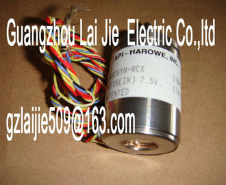
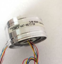
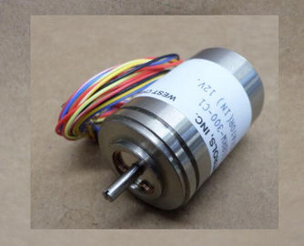
| Brand Name: | HAROWE |
| Certification: | CE |
| Model Number: | 15BRCX-602-F15A/15 |
| Minimum Order Quantity: | 1pcs |
|---|---|
| Packaging Details: | carton |
| Delivery Time: | in stock |
| Payment Terms: | T/T, Western Union, MoneyGram |
| Supply Ability: | 100pcs/week |
| HAROWE: | HAROWE | 15BRCX-602-F15A/15: | 15BRCX-602-F15A/15 |
|---|---|---|---|
| GERMANY: | GERMANY | Temperature: | 20-90 |
| Color: | Black | Dimension: | 90mm |
| Wire: | Wire |
| assignment and structure of the parameter data records (Page 44). The following parameter settings are possible? Hardware interrupt |
|
| high limit 1 Yes/No No Yes Channel --- 4) |
|
| Hardware interrupt low limit 1 |
Yes/No No Yes Channel --- 4)
? Hardware interrupt
high limit 2
Yes/No No Yes Channel --- 4)
? Hardware interrupt
low limit 2
Yes/No No Yes Channel --- 4)
1) If you enable diagnostics for multiple channels, you will receive an alarm surge on failure of the supply voltage because
each enabled channel will detect this fault.
You can prevent this message burst by assigning the diagnostics function to one channel only.
2) When "Wire break" diagnostics is disabled, the current limit of 1.185 mA applies to the value status. For measured
values below 1.185 mA, the value status is always: 0 = fault.
3) You can set the effective range of the diagnostics for each channel in the user program with data records 0 to 7.
4) You can set the current limit for wire break diagnostics, the "Hardware interrupt" parameter and the hardware interrupt
limits in the user program with data records 0 to Specifies the number of sub-cycles per isochronous data cycle for the for the oversampling
function.
Missing supply voltage L+
Enabling of the diagnostics, with missing or too little supply voltage L+.
Overflow
Enabling of the diagnostics if the measured value violates the high limit.
Underflow
Enabling of the diagnostics if the measured value violates the low limit.
Wire break
Enabling of the diagnostics if the module has no current flow or the current is too weak for
the measurement at the corresponding configured input or the applied voltage is too low.
Current limit for wire break diagnostics
Threshold for reporting wire breaks. The value can be set to 1.185 mA or 3.6 mA, depending
on the sensor used.The individual measured values are smoothed using filtering. The smoothing can be set in
4 levels.
Smoothing time = number of module cycles (k) x cycle time of the module.
The following figure shows after how many module cycles the smoothed analog value is
almost 100%, depending on the set smoothing. Is valid for each signal change at the analog
input.rupt 1 or 2
Enable a hardware interrupt at violation of high limit 1 or 2 or low limit 1 or 2.
Low limit 1 or 2
Specifies the low limit threshold that triggers hardware interrupt 1 or 2.
High limit 1 or 2
Specifies the high limit threshold that triggers hardware interrupt 1 or 2.
If the measuring range adjustment is enabled in addition to measured value scaling, first the
measuring range is adjusted and then the representation of the measuring range scaled.
table below shows an example of the combination of measured value scaling and measuring
range adjustmentThe following figures show examples of a configuration in STEP 7 (TIA Portal)In the configuration example, a measuring range adjustment of -4000 mV to 8000 mV is
displayed and additionally converted to a scaled high and low nominal range limit of 1.00 to
7.00.The section below includes the block diagram of the module and various wiring options.
You can find information on wiring the front connector, establishing a cable shield, etc in the
Wiring section of the /ET 200MP You may use and combine the different wiring options for all channels.
• Do not insert the potential jumpers included with the front connector!Meaning of the abbreviations used in the following figures:
Un+/Un- Voltage input channel n (voltage only)
In+/In- Current input channel n (current only)
L+ Supply voltage connection
M Ground connectionThe power supply element is plugged onto the front connector for powering the analog
module. Wire the supply voltage to terminals 41 (L+) and 44 (M). Use terminals 42 (L+) and
43 (M) to loop the potential to the next module.Analog-to-Digital Converter (ADC) CHx Channel or 8 x channel status (green/red)
② Electrical isolation RUN Status display LED (green)