 |
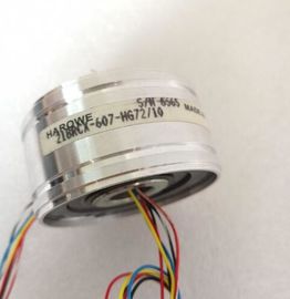
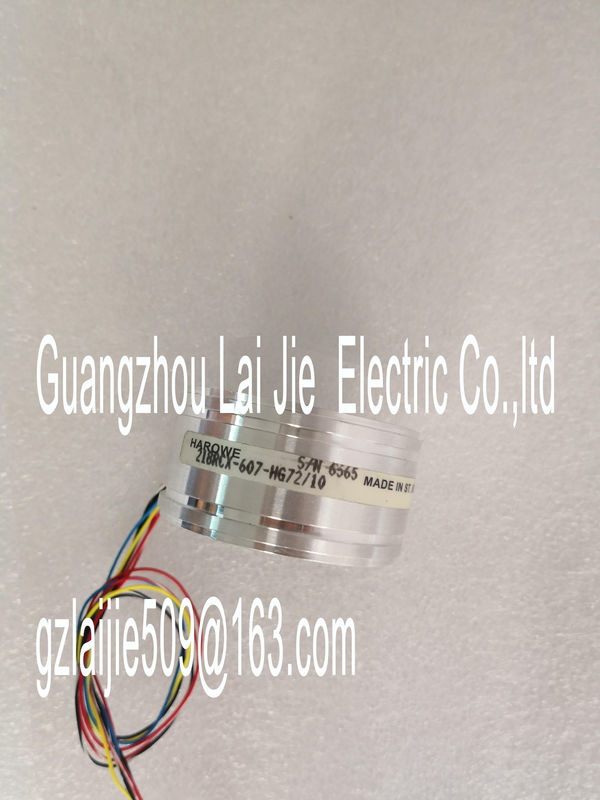
| Place of Origin: | GERMANY |
| Brand Name: | HAROWE |
| Certification: | CE |
| Model Number: | 15BRW-401-A51/20 |
| Minimum Order Quantity: | 1pcs |
|---|---|
| Packaging Details: | carton |
| Delivery Time: | in stock |
| Payment Terms: | T/T, Western Union, MoneyGram |
| Supply Ability: | 100pcs/week |
| HAROWE: | HAROWE | 15BRW-401-A51/20: | 15BRW-401-A51/20 |
|---|---|---|---|
| GERMANY: | GERMANY | Temperature: | 20-90 |
| Color: | Black | Dimension: | 90mm |
| Material: | Iron |
| (PROFINET IO only) 1 x 8-channel with value status for moduleinternal |
|
| shared input with up to 4 submodules AI 8xU/I HF MSI X |
|
| (PROFINET IO only) X |
(PROFINET IO only)
1 x 8-channel with value status for scaling
of measured values
AI 8xU/I HF Scale V14 or higher with HSP
0186
(PROFINET IO only)
X
(PROFINET IO only)The value status is always activated for the following module names:
● AI 8xU/I HF QI
● AI 8xU/I HF S QI
● AI 8xU/I HF MSI
● AI 8xU/I HF Scale
An additional bit is assigned to each channel for the value status. The value status bit
indicates if the read in digital value is valid. (0 = value is incorrect). The figure below shows the address space assignment with the configuration as 1 x 8-
channel module. You can freely assign the start address for the module. The addresses of
the channels are derived from the start address.
"IB x" stands, for example, for the module start address input byte xFor the configuration as a 8 x 1-channel module, the channels of the module are divided into
multiple submodules. The submodules can be assigned to different IO controllers when the
module is used in a shared device.
The number of usable submodules is dependent on the interface module used. Observe the
information in the manual for the particular interface module.
Contrary to the 1 x 8-channel module configuration, each of the eight submodules has a
freely assignable start address.The channels 0 to 7 of the module are copied in up to four submodules with configuration 1 x
8-channel module (Module-internal shared input, MSI). Channels 0 to 7 are then available
with identical input values in different submodules. These submodules can be assigned to up
to four IO controllers when the module is used in a shared device. Each IO controller has
read access to the same channels.
The number of IO controllers depends on the interface module used. Please observe the
information in the manual for the particular interface module.The meaning of the value status depends on the submodule on which it occurs.
For the 1st submodule (= basic submodule), the value status 0 indicates that the value is
incorrect.
For the 2nd to 4th submodule (=MSI submodule), the value status 0 indicates that the value
is incorrect or the basic submodule has not yet been configured (not ready).The following figure shows the assignment of the address space with submodules 1 andThe following figure shows the assignment of the address space with submodules 3 and 4.for configuration as 1 x 8-channel AI 8xU/I HF and Scale
The figure below shows the address space assignment for configuration as a 1 x 8-channel
module for scaling (Scale) of the measured values. You can freely assign the start address
for the module. The addresses of the channels are derived from the start address.
"IB x" stands, for example, for the module start address input byte x. You can find information on the Shared Input/Output (MSI/MSO) function in the section
Module-Internal Shared Input/Output (MSI/MSO) of the PROFINET with STEP 7 V13 The figure below shows the LED displays (status and error displays)
of AI 8xU/I HFThe following tables explain the meaning of the status and error displays. Remedial
measures for diagnostic alarms can be found in section Diagnostic alarms (Page 43).
RUN and ERROR LED
Table 5- 1 Status and error displays RUN and ERROR
LED Meaning Remedy
RUN ERROR
Off Off
Voltage missing or too low at backplane bus. • Switch on the CPU and/or the system power
supply modules.