|
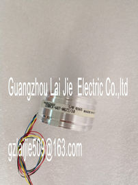
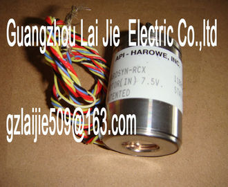
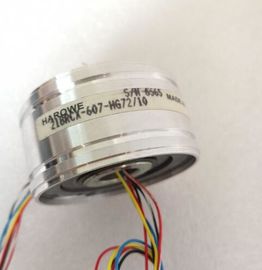
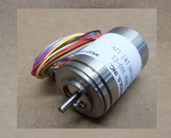
| Place of Origin: | GERMANY |
| Brand Name: | HAROWE |
| Certification: | CE |
| Model Number: | 15BRX700-F10AA |
| Minimum Order Quantity: | 1pcs |
|---|---|
| Packaging Details: | carton |
| Delivery Time: | in stock |
| Payment Terms: | T/T, Western Union, MoneyGram |
| Supply Ability: | 100pcs/week |
| HAROWE: | HAROWE | 15BRX700-F10AA: | 15BRX700-F10AA |
|---|---|---|---|
| GERMANY: | GERMANY | Temperature: | 20-90 |
| Wire: | Wire | Color: | Black |
| Dimension: | 90mm |
| record 0 and 1. The structure of the data records is available on the Internet in the "Manual | |
| for interface module IM 155-5 DP ST (6ES7155-5BA00-0AB0)Impedance of sensor circuit too high Use a different encoder type or modify | |
| the wiring, for example, using cables with larger cross-section |
Wire break between the module and
sensor
Connect the cable
Channel not connected (open) ? Disable diagnostics
? Connect the channel
Overflow 7H Measuring range violated Check the measuring range
Underflow 8H Measuring range violated Check the measuring range
Parameter assignment
error
10H ? The module cannot evaluate parameters
for the channel
? Incorrect parameter assignment.
Correct the parameter assignment
Load voltage missing 11H Supply voltage L+ of the module is
missing
Connect supply voltage L+ to module/channel
Diagnostics alarms with value status (QI)
If you configure the module with value status (QI), the module always checks all errors even
if the respective diagnostics is not enabled. But the module cancels the inspection as soon
as it detects the first error, regardless if the respective diagnostics has been enabled or not.
The result may be that enabled diagnostics may not be displayed.
Example: You have enabled "Underflow" diagnostics, but the module detects the previous
"Wire break" diagnostics and aborts after this error message. The "Underflow" diagnostics is
not detected.
Recommendation: To ensure that all errors are subjected to the diagnostics, select all check
boxes under "Diagnostics".Product type designation AI 8xU/I HF
Hardware functional status FS01
Firmware version V1.1.0
? FW update possible Yes
Product function
I&M data Yes; I&M0 to I&M3
Measuring range scalable No
Measured values scalable Yes
Measuring range adjustment Yes
Engineering with
STEP 7 TIA Portal can be configured/integrated
as of version
V14 / -
STEP 7 can be configured/integrated as of version V5.5 SP3 / -
PROFIBUS as of GSD version/GSD revision V1.0 / V5.1
PROFINET as of GSD version/GSD revision V2.3 / -
Operating mode
Oversampling No
MSI Yes
CiR Configuration in RUN
Configuration in RUN possible Yes
Calibration in RUN possible Yes
Supply voltage
Rated value (DC) 24 V
Valid range, low limit (DC) 20.4 V
Valid range, high limit (DC) 28.8 V
Reverse polarity protection Yes
Input current
Current consumption, max. 50 mA; with 24 V DC supply
Power
Power consumption from the backplane bus 0.85 W
Power loss
Power loss, typ. 1.9 WConfigurable Yes
Level: None Yes
Level: Weak Yes
Level: Medium Yes
Level: Strong Yes
Encoders
Connection of the signal encoders
For voltage measurement Yes
for current measurement as 2-wire transducer Yes; with external transmitter supply
for current measurement as 4-wire transducer Yes
Errors/accuracies
Linearity error (in relation to input range), (+/-) 0.02%
Temperature error (in relation to input range), (+/-) 0.005%/K
Crosstalk between the inputs, max. -80 dB
Repeat accuracy in settled state at 25 °C (in relation
to input range), (+/-)
0.02%
Operational limit in overall temperature range
Voltage in relation to input range, (+/-) 0.1%
Current in relation to input range, (+/-) 0.1%
Basic error limit (operational limit at 25 °C)
Voltage in relation to input range, (+/-) 0.05%
Current in relation to input range, (+/-) 0.05%
Interference voltage suppression for f = n x (f1 +/-
1 %), f1 = interference frequency
Series-mode interference (peak of the interference
< rated value of the input range), min.