|
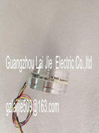
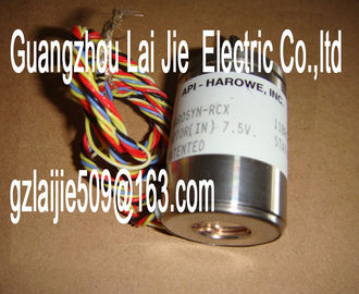
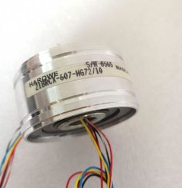
| Place of Origin: | GERMANY |
| Brand Name: | HAROWE |
| Certification: | CE |
| Model Number: | 15MA6WIRE16IN |
| Minimum Order Quantity: | 1PCS |
|---|---|
| Packaging Details: | CARTON |
| Delivery Time: | IN STOCK |
| Payment Terms: | T/T, Western Union, MoneyGram |
| Supply Ability: | 100PCS/WEEK |
| HAROWE: | HAROWE | 15MA6WIRE16IN: | 15MA6WIRE16IN |
|---|---|---|---|
| GERMANY: | GERMANY | Temperature: | 20-90 |
| Color: | Black | Dimension: | 90mm |
| Wire: | Wire | MATERIAL: | IRON |
| 80 dB; in Standard mode, 40 dB in Fast mode Common mode voltage, max. 60 V DC / 30 V AC |
|
| Common mode interference, min. 80 dB Isochronous mode |
|
| Isochronous mode (application synchronized up to terminal) |
No
Interrupts/diagnostics/status information
Diagnostics function Yes
Interrupts
Diagnostic interrupt Yes
Limit interrupt Yes; two high limits and two low limits each
Diagnostics alarms
Monitoring of supply voltage Yes
Wire break Yes; only for 1 to 5 V and 4 to 20 mA
Overflow/underflow YesRUN LED Yes; green LED
ERROR LED Yes; red LED
Monitoring of supply voltage (PWR LED) Yes; green LED
Channel status display Yes; green LED
For channel diagnostics Yes; red LED
For module diagnostics Yes; red LED
Electrical isolation
Electrical isolation of channels
Between the channels Yes
Between the channels, in groups of 1
Between the channels and backplane bus Yes
Between the channels and power supply of the
electronics
Yes
Permitted potential difference
Between different circuits 60 V DC / 30 V AC; Isolation measured for 120 V
AC basic isolation: Between the channels and
supply voltage L+, between the channels and the
backplane bus, between the channels
Isolation
Isolation tested with 2000 V DC between the channels and the supply
voltage L+, 2000 V DC between the channels and
the backplane bus, 2000 V DC between the
channels, 707 V DC (type test) between the supply
voltage L+ and the backplane bus
Ambient conditions
Ambient temperature during operation
Horizontal mounting position, min. 0 °C
Horizontal mounting position, max. 60 °C
Vertical mounting position, min. 0 °C
Vertical mounting position, max. 40 °C
Distributed mode
Prioritized startup Yes
Dimensions
Width 35 mm
Height 147 mm
Depth 129 mm
Weights
Weight, approx. 280 gThis appendix contains the dimensional drawing of the module installed on a mounting rail
and with a shield bracket. Always adhere to the specified dimensions for installations in
cabinets, control rooms, etc.The data records of the module have an identical structure, regardless of whether you
configure the module with PROFIBUS DP or PROFINET IO.
Dependencies for configuration with GSD file
When configuring the module with a GSD file, remember that the settings of some
parameters are dependent on each other. The parameters are only checked for plausibility
by the module after the transfer to the module.
The following table lists the parameters that depend on one another.
Table B- 1 Dependencies of parameters for configuration with GSD fileYou have the option to assign module parameters in RUN (e.g., the voltage or current values
of selected channels can be edited in RUN without having an effect on the other channels).
Parameter assignment in RUN
The WRREC instruction is used to transfer the parameters to the module using data records
0 to 7. The parameters set in STEP 7 do not change in the CPU, which means the
parameters set in STEP 7 are still valid after a restart.
The parameters are only checked for plausibility by the module after the transfer to the
module.
Output parameter STATUS
The module ignores errors that occurred during the transfer of parameters with the WRREC
instruction and continues operation with the previous parameter assignment. However, a
corresponding error code is written to the STATUS output parameter.
The description of the WRREC instruction and the error codes is available in the STEP 7 If the module is operated behind a PROFIBUS DP interface module, the parameter data
records 0 and 1 are not read back. You obtain the diagnostics data records 0 and 1 with the
read back parameter data records 0 and 1. You can find additional information in the
Interrupts section of the manual for the PROFIBUS DP interface module on the InternetFor the configuration as a 1 x 8-channel module, the parameters are located in data records
0 to 7 and are assigned as follows:
● Data record 0 for channel 0
● Data record 1 for channel 1● Data record 6 for channel 6
● Data record 7 for channel 7
For configuration 8 x 1-channel, the module has 8 submodules with one channel each. The
parameters for the channel are available in data record 0 and are assigned as follows:
● Data record 0 for channel 0 (submodule 1)
● Data record 0 for channel 1 (submodule 2)