|
| Place of Origin: | GERMANY |
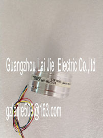
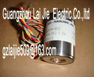
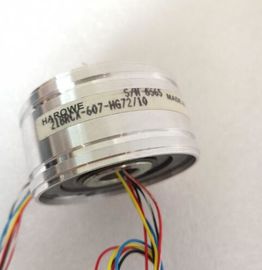
| Brand Name: | HAROWE |
| Certification: | CE |
| Model Number: | 18DT-205-A-4 |
| Minimum Order Quantity: | 1pcs |
|---|---|
| Packaging Details: | carton |
| Delivery Time: | in stock |
| Payment Terms: | T/T, Western Union, MoneyGram |
| Supply Ability: | 100pcs/week |
| HAROWE: | HAROWE | 18DT-205-A-4: | 18DT-205-A-4 |
|---|---|---|---|
| Material: | Iron | Color: | Black |
| Temperature: | 20-90 | Dimension: | 90mm |
| Germany: | Germany | Wire: | Wire |
| Data record 0 for channel 6 (submodule 7) ● Data record 0 for channel 7 (submodule 8) |
|
| Address the respective submodule for data record transfer. The structure of the parameter data record differs depending on the configuration: | |
| 28 bytes data length for configuration without scaling of the measured values, see section Structure of the parameter data records without scaling of measured values (Page 52). |
40 bytes data length for configuration with scaling of the measured values, see section
Structure of the parameter data records with scaling of measured values (Page 55).Structure of a data record without scaling of the measured values
The figure below shows the structure of data record 0 for channel 0 as an example. The
structure is identical for channels 1 to 7. The values in byte 0 and byte 1 are fixed and may
not be changed.
Enable a parameter by setting the corresponding bit to "1Structure of a data record with scaling of the measured values
The example in the figure below shows the structure of data record 0 for channel 0 for
scaling of measured values. The structure is identical for channels 1 to 7. The values in byte
0 and byte 1 are fixed and may not be changed.
Enable a parameter by setting the corresponding bit to "1".
Codes for measurement types/measuring ranges and limits for hardware interrupts
(Page 58) The following table lists all measuring types of the analog input module along with their
codes. Enter these codes in byte 2 of the respective data record.
Table B- 2 Code for the measuring type
Measurement type Code
Deactivated 0000 0000
Voltage 0000 0001
Current 4-wire transducer 0000 0010
Current 2-wire transducer 0000 0011The following table lists all measuring ranges of the analog input module along with their
codes. Enter these codes in byte 3 of the respective data record.
Table B- 3 Code for the measuring range
Measuring range Code
Voltage
±2.5 V
±5 V
±10 V
1 V to 5 V
0000 0111
0000 1000
0000 1001
0000 1010
Current 4-wire transducer
0 mA to 20 mA
4 mA to 20 mA
±20 mA
0000 0010
0000 0011
0000 0100
Current 2-wire transducer
4 mA to 20 mA 0000 001pt limits
The following tables list the valid hardware interrupt limits. The limit values depend on the
selected measuring type and range. The values that you can set for hardware interrupts
(high/low limit) must not exceed the respective rated measuring range.
Enter the limits in bytes 12 to 19 or 12 to 27 of the corresponding data record.
Table B- 4 Limits of hardware interrupts for voltage and currentThis appendix shows the analog values for all measuring ranges supported by the AI 8xU/I
HF analog module.
Measured value resolution
Each analog value is written left aligned to the tags. The bits marked with "x" are set to "0".
Table C- 1 Resolution of the analog valuesThe tables below set out the digitized representation of the input ranges separately for
bipolar and unipolar input ranges. The resolution is 16 bits.The following tables list the decimal and hexadecimal values (codes) of the possible voltage
measuring ranges.
Table C- 4 Voltage measuring ranges ±10 V, ±5 V and ±2.5 VThe following tables list the decimal and hexadecimal values (codes) of the possible current
measuring ranges.
Table C- 6 Current measuring range ±20 mAError events initiate a diagnostics entry and trigger a diagnostics interrupt if configured
accordingly.