 |
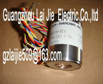
| Place of Origin: | GERMANY |
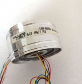
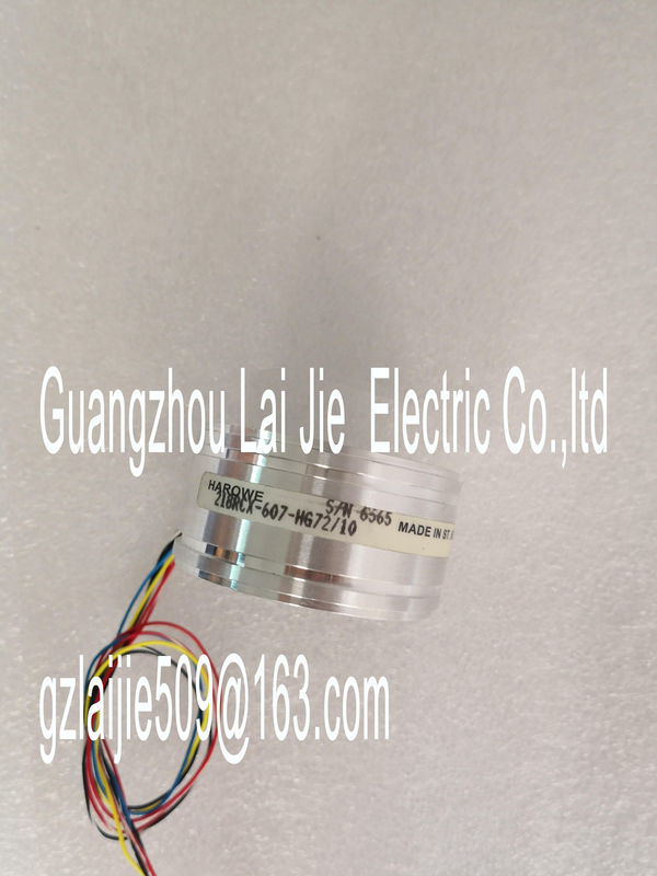
| Brand Name: | HAROWE |
| Certification: | CE |
| Model Number: | 21BRCX-500-F8-01 |
| Minimum Order Quantity: | 1pcs |
|---|---|
| Packaging Details: | carton |
| Delivery Time: | in stock |
| Payment Terms: | T/T, Western Union, MoneyGram |
| Supply Ability: | 100pcs/week |
| HAROWE: | HAROWE | 21BRCX-500-H: | 21BRCX-500-H |
|---|---|---|---|
| GERMANY: | GERMANY | Temperature: | 20-90 |
| Color: | Black | Dimension: | 90mm |
| Wire: | Wire |
| 0 mA to 20 mA Yes -20 mA to +20 mA Yes |
|
| 4 mA to 20 mA Yes Connection of actuators |
|
| for voltage output two-wire connection Yes for voltage output four-wire connection Yes |
for current output two-wire connection Yes
Load resistance (in the rated output range)
for voltage outputs, min. 1 kΩ
for voltage outputs, capacitive load, max. 100 nF
for current outputs, max. 500 Ω
for current outputs, inductive load, max. 1 mH
Cable length
shielded, max. 200 mmax.
16 bit
Conversion time (per channel) 50 µs; regardless of the number of activated
channels
Settling time
for resistive load 30 µs; see additional description in the manual
for capacitive load 100 µs; see additional description in the manual
for inductive load 100 µs; see additional description in the manualOutput ripple (relative to output range, bandwidth
0 to 50 kHz), (+/-)
0.02%
Linearity error (relative to output range), (+/-) 0.15%
Temperature error (in relation to output range),
(+/-)
0.002%/K
Crosstalk between outputs, max. -100 dB
Repeat accuracy in settled state at 25 °C (in relation
to output range), (+/-)
0.05%
Operational limit in overall temperature range
Voltage in relation to output range, (+/-) 0.3%
Current in relation to output range, (+/-) 0.3%
Basic error limit (operational limit at 25 °C)
Voltage in relation to output range, (+/-) 0.2%
Current in relation to output range, (+/-) 0.2%
Isochronous mode
Isochronous mode (application synchronized up to
terminal)
Yes
Execution and activation time (TCO), min. 100 µs
Bus cycle time (TDP), min. 250 µs
Interrupts/diagnostics/status information
Diagnostics function Yes
Substitute values can be applied Yes
Interrupts
Diagnostic interrupt Yes
Diagnostics alarms
Monitoring of supply voltage Yes
Wire break Yes; only for output type current
Short-circuit Yes; only for output type voltage
Overflow/underflow Yes
Diagnostics indicator LED
RUN LED Yes; green LED
ERROR LED Yes; red LED
Monitoring of supply voltage (PWR LED) Yes; green LED
Channel status display Yes; green LED
For channel diagnostics Yes; red LED
For module diagnostics Yes; red LED
Electrical isolation
Electrical isolation of channels
Between the channels No
Between the channels, in groups of 8
Between the channels and backplane bus Yes
Between the channels and load voltage L+ YesThe following trends show the number of channels (CHx) that can be used simultaneously in
horizontal and vertical installation of the automation system/ET 200MP distributed
I/O system depending on the ambient temperature.All eight channels can be used in the case of voltage outputs with load resistances > 5 kΩ
and ambient temperatures up to 40° (vertical installation) or up to 60° (horizontal installation).
Settling times for voltage outputs
The settling time for voltage outputs is influenced mainly by the capacitive loadThe settling time for current outputs increases when the load impedance risesThis appendix contains the dimensional drawing of the module installed on a mounting rail
and with a shield bracket. Always observe the specified dimensions for installation in
cabinets, control rooms, etcThe data records of the module have an identical structure, regardless of whether you
configure the module with PROFIBUS DP or PROFINET IO.
Dependencies for configuration with GSD file
When configuring the module with a GSD file, remember that the settings of some
parameters are dependent on each other. The parameters are only checked for plausibility
by the module after the transfer to the module.
The following table lists the parameters that depend on one another.You have the option to assign module parameters in RUN (e.g., the voltage or current values
of selected channels can be edited in RUN without having an effect on the other channels).
Parameter assignment in RUN
The WRREC instruction is used to transfer the parameters to the module using data records
64 to 71. The parameters set in STEP 7 do not change in the CPU, which means the
parameters set in STEP 7 are still valid after a restart.
The parameters are only checked for plausibility by the module after the transfer to the
module.
Output parameter STATUS
The module ignores errors that occurred during the transfer of parameters with the WRREC
instruction and continues operation with the previous parameter assignment. However, a
corresponding error code is written to the STATUS output parameter.
The description of the WRREC instruction and the error codes is available in the STEP 7
online help.If the module is operated behind a PROFIBUS DP interface module, the parameter data
records 0 and 1 are not read back. You obtain the diagnostics data records 0 and 1 with the
read back parameter data records 0 and 1. You can find additional information in the
Interrupts section of the manual for the PROFIBUS DP interface module on the The channel parameters in data records 64 to 71 are available for 1x 8-channel configuration
and are assigned as follows:
● Data record 64 for channel 0
● Data record 65 for channel 1
● ...
● Data record 70 for channel 6
● Data record 71 for channel 7
For configuration 8 x 1-channel, the module has 8 submodules with one channel each. The
parameters for the channel are available in data record 64 and are assigned as follows:
● Data record 64 for channel 0 (submodule 1)
● Data record 64 for channel 1 (submodule 2)
● ...
● Data record 64 for channel 5 (submodule 6)
● Data record 64 for channel 6 (submodule 7)
● Data record 64 for channel 7 (submodule 8)
Address the respective submodule for data record transfer.The figure below shows the structure of data record 64 for channel 0 as an example. The
structure is identical for channels 1 to 7. The values in byte 0 and byte 1 are fixed and may
not be changed.
Enable a parameter by setting the corresponding bit to "1".
he following table lists all output types of the analog output module along with their codes.
Enter these codes at byte 2 of the data record for the corresponding channel (see the
previous figure).
Table B- 2 Code for the output type
Output type Code
Deactivated 0000 0000
Voltage 0000 0001
Current 0000 0010
Codes for the output ranges
The table below contains all output ranges of the analog output module with their codes.
Enter these codes at byte 3 of the data record for the corresponding channel (see the
previous figure)The following table lists all output ranges for the valid substitute values. Enter these
substitute values at bytes 6 and 7 of the data record for the corresponding channel (see the
previous figure). You can find the binary representation of the output ranges in section
Representation of analog values (Page 46).This appendix describes the analog values for all output ranges supported by the AQ 8xU/I
HS analog module.
Measured value resolution