|
| Place of Origin: | GERMANY |
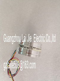
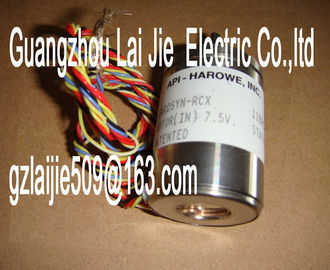
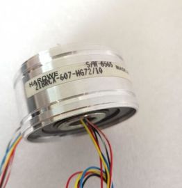
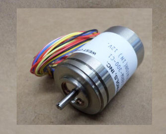
| Brand Name: | HAROWE |
| Certification: | CE |
| Model Number: | 21BRCX-500-F8 |
| Minimum Order Quantity: | 1pcs |
|---|---|
| Packaging Details: | carton |
| Delivery Time: | in stock |
| Payment Terms: | T/T, Western Union, MoneyGram |
| Supply Ability: | 100pcs/week |
| HAROWE: | HAROWE | 21BRCX-500-F8: | 21BRCX-500-F8 |
|---|---|---|---|
| Material: | Iron | Color: | Black |
| Temperature: | 20-90 | Dimension: | 90mm |
| Wire: | Wire | Germany: | Germany |
| Abbreviations used Meaning of the abbreviations used in the figures below: |
|
| QVn Voltage output channel QIn Current output channel |
|
| Sn+/Sn- Sense line channel L+ Supply voltage connection |
M Ground connection
MANA Reference potential of the analog circuit
CHx Channel or display of the channel status
PWR Display for the supply voltage
Pin assignment for the power supply element
The power supply element is plugged onto the front connector for powering the analog
module. Wire the supply voltage to terminals 41 (L+) and 44 (M). Use terminals 42 (L+) and
43 (M) to loop the potential to the next module.The example in the figure below shows the pin assignment for a voltage measurement.
● 2-wire connection, no compensation for line impedance.
● 4-wire connection with compensation for line impedance is displayed.2-wire connection (jumper at the front connector) CHx Channel or 8 x channel status (green/red)
② 4-wire connection RUN Status display LED (green)
③ Digital Analog Converter (DAC) ERROR Error display LED (red)
④ Backplane bus interface PWR LED for power supply (green)The following figure shows an example of the terminal assignment for current output
circuitry.Load on current outputs CHx Channel or 8 x channel status (green/red)
② Digital Analog Converter (DAC) RUN Status display LED (green)
③ Backplane bus interface ERROR Error display LED (red)
④ Supply voltage via power supply element PWR LED for power supply (greThe module is set to voltage output type by default with output range ±10 V. You need to edit
the module parameters with STEP 7 if you want to use a different output range or output
type.
Output type and output ranges
Output type Output range Representation of analog
values
Voltage 1 V to 5 V
0 V to 10 V
±10 V
See Appendix Representation
of analog
values in the voltage
output ranges
(Page 48).
Current 0 mA to 20 mA
4 mA to 20 mA
±20 mA
See Appendix Representation
of analog
values in the current
output ranges
(Page 49).
Deactivated -
The tables of the output ranges, overflow, overrange, etc. are available in the Appendix
Representation of analog values (Page 46The AQ 8xU/I HS is usually already integrated in the hardware catalog of STEP 7
(TIA Portal). In this case, STEP 7 (TIA Portal) checks the configured properties for
plausibility during configuration.
However, you can also assign parameters to the module by means of a GSD file and the
configuration software of any provider. The module does not check the validity of the
configured properties until after the configuration has been loaded.
When you assign the module parameters in STEP 7, you use various parameters to specify
the module properties. The following table lists the configurable parameters. The effective
range of the configurable parameters depends on the type of configuration. The following
configurations are possible:
● Central operation with a CPU
● Distributed operation on PROFINET IO in an ET 200MP system
● Distributed operation on PROFIBUS DP in an ET 200MP system
When assigning parameters in the user program, use the WRREC instruction to transfer the
parameters to the module by means of data records; refer to chapter Parameter assignment
and structure of the parameter data records (Page 42).
Table 4- 1 Configurable parameters and their defaultsIf you enable diagnostics for multiple channels, you will receive an alarm surge on failure of the supply voltage because
each enabled channel will detect this fault.
You can prevent this message burst by assigning the diagnostics function to one channel only.
2) You can set the effective range of the diagnostics for each channel in the user program with data records 64 to 71.
3) You can configure the setting "Output substitute value" and the substitute value in the user program by means of data
records 64 to 71.
Short-circuit detection
The diagnostics for short circuit to ground can be configured for the voltage output type. A
short-circuit detection is not possible for small output values; the output voltages must
therefore be below -0.5 V or above +0.5 V.
Open-circuit detection
The diagnostics for open circuit can be configured for the current output type. An open-circuit
detection is not possible for small output values; the output voltages must therefore be below
-3 mA or above +3 mA.Specifies the number of sub-cycles per isochronous data cycle for the for the