|
| Place of Origin: | GERMANY |
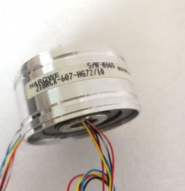
| Brand Name: | HAROWE |
| Certification: | CE |
| Model Number: | 21BRCX-500-F24 |
| Minimum Order Quantity: | 1pcs |
|---|---|
| Packaging Details: | carton |
| Delivery Time: | in stock |
| Payment Terms: | T/T, Western Union, MoneyGram |
| Supply Ability: | 100pcs/week |
| HAROWE: | GERMANY | Material: | Iron |
|---|---|---|---|
| Color: | Black | Temperature: | 20-90 |
| Dimension: | 90mm | Wire: | Wire |
| Germany: | Germany |
| Device-specific parameters (GSD file) Dependent parametersOnly for measurement type current with measuring range 4 to 20 mA. | |
| Wire break Only for measurement type resistance, thermistor RTD, thermocouple TC, voltage with measuring range 1V to 5 V and current with measuring |
|
| range 4 to 20 mA. Common mode error Only for measuring type voltage, current and thermocouple TC. |
range 4 to 20 mA.
Common mode error Only for measuring type voltage, current and thermocouple TC.
structure of channels 1 to 3 is identical. The values in byte 0 and byte 1 are fixed and may
not be changed.
Enable a parameter by setting the corresponding bit to "1"The following table lists all measurement types of the analog input module along with their
codes. Enter these codes at byte 2 of the data record for the corresponding channel (see the
figure Structure of data record 0: Bytes 7 to 27)Current, 2-wire transmitter 0000 0011
Current, 4-wire transmitter 0000 0010
Resistance, 4-wire connection *) **) 0000 0100
Resistance, 3-wire connection *) **) 0000 0101
Resistance, 2-wire connection *) ***) 0000 0110
Thermal resistor linear, 4-wire connection *) 0000 0111
Thermal resistor linear, 3-wire connection *) 0000 1000
Thermocouple 0000 1010
*) only possible for channels 0 and 2
**) only for the following measuring ranges: 150 Ω, 300 Ω, 600 Ω, 6 kΩ
***) only for measuring range PTCWhen you set one of the following measurement types at channel 0 or channel 2:
● Resistance, 4-wire connection
● Resistance, 3-wire connection
● Resistance, 2-wire connection
● Thermal resistor linear, 4-wire connection
● Thermal resistor linear, 3-wire connection
then one of the following channels must be disabled.
Example:
You have configured "Resistance, 4-wire connection" at channel 0; channel 1 must be
disabled. You have configured "Resistance, 2-wire connection" at channel 2; channel 3 must
be disabled.The following table lists all measuring ranges of the analog input module along with their
codes. Enter these codes accordingly at byte 3 of the data record for the corresponding
channel (see the figure Structure of data record 0: Bytes 7 to 27).The following table lists all temperature coefficients along with their codes for temperature
measurements with the thermal resistors. These codes must be entered in byte 4 of the
corresponding data recordThe values that you can set for hardware interrupts (high/low limit) must not violate the
over/underrange of the respective rated measuring range.
The following tables list the valid hardware interrupt limits. The limits depend on the selected
measurement type and measuring rangThe WRREC instruction is used to transfer the reference junction temperature via data
record 192 to data record 195 to the module.
The description of the WRREC instruction can be found in the online help from STEP 7.
If you have set the "Dynamic reference temperature" value for the "Reference junction"
parameter, the module expects a new data record at least every 5 minutes. If the module
does not receive a new data record within this time, it generates the "Reference channel
error" diagnostics message.
Assignment of data record and channel
The following assignment applies if no submodules (1 x 4-channel) are configured for the
module:
● Data record 192 for channel 0
● Data record 193 for channel 1
● Data record 194 for channel 2
● Data record 195 for channel 3
Structure of data record 192 for dynamic reference temperature
The following figure shows an example of the structure of data record 192 for channel 0. The
structure for data records 193 to 195 is identical.
Figure B-3 Structure of data record 19ou can enter the selectable values a