|
| Place of Origin: | GERMANY |
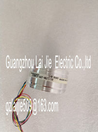
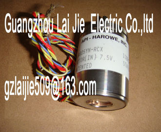
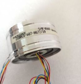
| Brand Name: | HAROWE |
| Certification: | CE |
| Model Number: | 21BRCX-500-F10 |
| Minimum Order Quantity: | 1pcs |
|---|---|
| Packaging Details: | carton |
| Delivery Time: | in stock |
| Payment Terms: | T/T, Western Union, MoneyGram |
| Supply Ability: | 100pcs/week |
| HAROWE: | HAROWE | Material: | Iron |
|---|---|---|---|
| Color: | Black | Temperature: | 20-90 |
| Dimension: | 90mm | Wire: | Wire |
| Germany: | Germany |
| connections, use equipotential cables Reference channel |
|
| error 15H Reference temperature of the reference |
|
| junction for the TC channel being operated with compensation is |
invalid.
Check the resistance thermometer. For
the compensation with data record, restore
communication to the module/station.
Channel temporarily
unavailable
1FH User calibration is active.
Channel currently not providing
current/valid values.
Exit user calibration. you configure the module with value status (QI), the module always checks all errors even
if the respective diagnostics is not enabled. But the module cancels the inspection as soon
as it detects the first error, regardless if the respective diagnostics has been enabled or not.
The result may be that enabled diagnostics may not be displayed.
Example: You have enabled the diagnostics "Underflow", but the module detects the
previous diagnostics "Wire break" and cancels after this error message. The "Underflow"
diagnostics is not detected.
Recommendation: To ensure that all errors get diagnosed, select all check boxes under
"DiagnosticsHardware version I01
Firmware version V1.0.0
Product function
I&M data Yes; I&M0 to I&M3
Engineering with
STEP 7 TIA Portal can be configured/integrated
as of version
V13 / V13.0.2
STEP 7 can be configured/integrated as of version V5.5 SP3 / -
PROFIBUS as of GSD version/GSD revision V1.0 / V5.1
PROFINET as of GSD version/GSD revision V2.3 / -
Operating mode
MSI Yes
CiR Configuration in RUN
Reconfiguration in RUN possible Yes
Calibration in RUN possible Yes
Supply voltage
Rated value (DC) 24 V
Valid range, low limit (DC) 20.4 V
Valid range, high limit (DC) 28.8 V
Reverse polarity protection Yes
Input current
Current consumption, max. 140 mA; with 24 V DC supply
Encoder supply
24 V encoder supply
Short-circuit protection Yes
Output current, max. 53 mA
Power
Power consumption from backplane bus 0.7 W
Power loss
Power loss, typ.Number of analog inputs 4
Number of analog inputs with current measurement
4
Number of analog inputs for voltage measurement 4
Number of analog inputs for resistance/resistance
thermometer measurement
2
Number of analog inputs with thermocouple
measurement
4
Permissible input voltage for voltage input (destruction
limit), max.
28.8 V
Permissible input current for current input (destruction
limit), max.
40 mA
Technical unit for temperature measurement adjustable
Yes
Input ranges (rated values), voltages
1 V to 5 V Yes
Input resistance (1 V to 5 V) 100 kΩ
-1 V to +1 V Yes
Input resistance (-1 V to +1 V) 10 MΩ
-10 V to +10 V Yes
Input resistance (-10 V to +10 V) 100 kΩ
-2.5 V to +2.5 V Yes
Input resistance (-2.5 V to +2.5 V) 10 MΩ
-250 mV to +250 mV Yes
Input resistance (-250 mV to +250 mV) 10 MΩ
-5 V to +5 V Yes
Input resistance (-5 mV to +5 V) 100 kΩ
-50 mV to +50 mV Yes
Input resistance (-50 mV to +50 mV) 10 MΩ
-500 mV to +500 mV Yes
Input resistance (-500 mV to +500 mV) 10 MΩ
-80 mV to +80 mV Yes
Input resistance (-80 mV to +80 mV) 10 MΩ
Input ranges (rated values), currents
0 mA to 20 mA Yes
Input resistance (0 mA to 20 mA) 25 Ω; plus approx. 42 ohm for overvoltage protection
by PTC
-20 mA to +20 mA Yes
Input resistance (-20 mA to +20 mA) 25 Ω; plus approx. 42 ohm for overvoltage protection
by PTC
4 mA to 20 mA Yes
Input resistance (4 mA to 20 mA) 25 Ω; plus approx. 42 ohm for overvoltage protection
by PTCechnical unit for temperature measurement °C/°F/K
Temperature compensation
• Configurable Yes
• Internal temperature compensation Yes
• Compensation for 0 °C reference point temperature
Yes, fixed value can be set
Resistance thermometer (RTD)
Technical unit for temperature measurement °C/°F/K
Cable length
Shielded cable length, max. 800 m; for U/I, 200 m for R/RTD, 50 m for TC
Analog value formation
Integration and conversion time / resolution per
channel
Resolution with overrange (bit including sign),
max.
16 bit
Configurable integration time Yes
Integration time, ms 2,5 / 16,67 / 20 / 100
Basic conversion time, including integration time,
ms
9 / 23 / 27 / 107 ms
• Additional conversion time for wire break monitoring
9 ms
• Additional conversion time for wire break
measurement
150Ohm, 300Ohm, 600Ohm, Pt100, Pt200,
Ni100: 2ms 6000Ohm, Pt500, Pt1000, Ni1000,
LG-Ni1000, PTC: 4ms
Interference voltage suppression at interference
frequency f1 in Hz
400 / 60 / 50 / 10
Smoothing of the measured values
Configurable Yes
Level: None Yes
Level: Weak Yes
Level: Medium Yes
Level: Strong Yes
Encoders
Connection of the signal encoders
For voltage measurement Yes
for current measurement as 2-wire transducer Yes
Load of 2-wire transmitter, max. 820 Ω
for current measurement as 4-wire transducer Yes
for resistance measurement with two-wire connection
Yes; only for PTC
for resistance measurement with three-wire connection
Yes; all measuring ranges except PTC; internal