 |
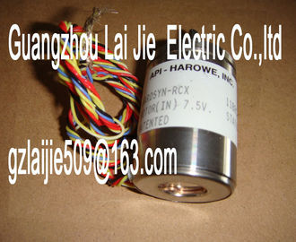
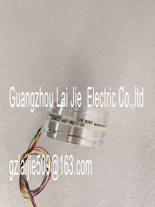
| Place of Origin: | GERMANY |
| Brand Name: | HAROWE |
| Certification: | CE |
| Model Number: | 21BRCX-500-F |
| Minimum Order Quantity: | 1pcs |
|---|---|
| Packaging Details: | carton |
| Delivery Time: | in stock |
| Payment Terms: | T/T, Western Union, MoneyGram |
| Supply Ability: | 100pcs/week |
| HAROWE: | HAROWE | 21BRCX-500-F: | 21BRCX-500-F |
|---|---|---|---|
| GERMANY: | GERMANY | Temperature: | 20-90 |
| Color: | Black | Dimension: | 90mm |
| Material: | Iron |
| configuration is set. --- On Off |
|
| Module is configured. On Flashes |
|
| Indicates module errors (at least one error at one channel, e.g., wire break). |
Evaluate the diagnostics data and eliminate the
error (e.g., wire break).
Flashes Flashes
Hardware defective. Replace the modulSupply voltage L+ to module too low or missing Check supply voltage L+.
On
Supply voltage L+ is present and OK.Channel disabled. ---
On
Channel configured and OK. ---
On
Channel is configured (channel error pending).
Diagnostics alarm: e.g. wire break
Check the wiring
Disable diagnostics.Analog input module AI 4xU/I/RTD/TC ST supports the following diagnostics and hardware
interrupts.
Diagnostics interrupt
The module generates a diagnostics interrupt at the following events:
● No supply voltage L+
● Wire break
● Overflow
● Underflow
● Common mode error
● Reference junction
Hardware interrupt
The module generates a hardware interrupt at the following events:
● Low limit violated 1
● High limit violated 1
● Low limit violated 2
● High limit violated 2
For detailed information on the error event, refer to the hardware interrupt organization block
with the "RALRM" instruction (read additional interrupt info) and to the STEP 7 online help.
The module channel that triggered the hardware interrupt is entered in the start information
of the organization block. The diagram below shows the assignment to the bits of double
word 8 in local datahardware interrupt for high limit 1 first. The configured value for high limit 2 is irrelevant. After
processing the hardware interrupt for high limit 1, the module triggers the hardware interrupt
for high limit 2.
The module has the same reaction when the low limits are reached at the same time. If the
two low limits 1 and 2 are reached at the same time, the module always signals the
hardware interrupt for low limit 1 first. After processing the hardware interrupt for low limit 1,
the module triggers the hardware interrupt for low limit 2.(User Structure Identifier)
W#16#0001 Additional interrupt info for hardware interrupts
of the I/O module
2
The channel that triggered the hardware interrupt follows.
Channel B#16#00 to B#16#n Number of the event-triggering channel (n =
number of module channels -1)
1
It is followed by the event that triggered the hardware interrupt.
Event B#16#03 Low limit violated 1 1
B#16#04 High limit violated 1
B#16#05 Low limit violated 2
B#16#06 High limit violated 2A diagnostics alarm is output for each diagnostics event and the ERROR LED flashes on the
module. The diagnostics alarms can, for example, be read from the diagnostics buffer of the
CPU. You can evaluate the error codes with the user programupply voltage L+ of the module is
missing
Connect supply voltage L+ to module/channel
Wire break 6H Impedance of encoder circuit too
high
Use a different encoder type or modify the
wiring, for example, using cables with
larger cross-section
Wire break between the module and
sensor
Connect the cable
Channel not connected (open) • Disable diagnostics
• Connect the channel
Overflow 7H Measuring range violated Check the measuring range
Underflow 8H Measuring range violated Check the measuring range
Common mode error 118H Valid common mode voltage exceeded
Causes when a 2WT is connected,
e.g.:
• Wire break
• Galvanic connection to MANA
Check the wiring, e.g. sensor ground