|
| Place of Origin: | GERMANY |
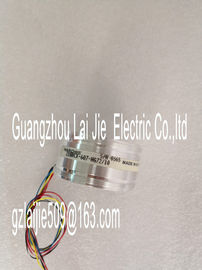
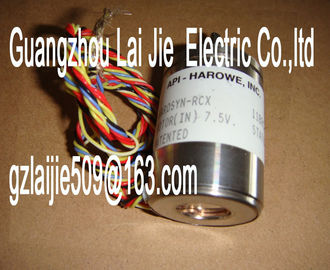
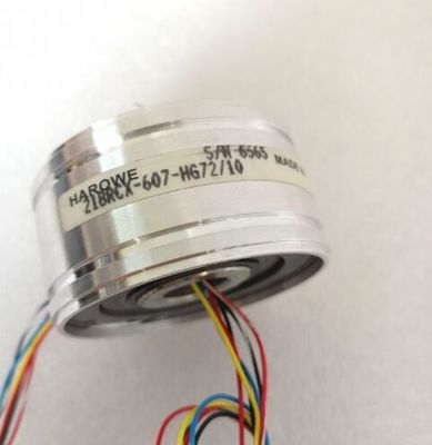
| Brand Name: | HAROWE |
| Certification: | CE |
| Model Number: | 21BRCX-500-E66 |
| Minimum Order Quantity: | 1pcs |
|---|---|
| Packaging Details: | carton |
| Delivery Time: | in stock |
| Payment Terms: | T/T, Western Union, MoneyGram |
| Supply Ability: | 100pcs/week |
| HAROWE: | HAROWE | 21BRCX-500-E66: | 21BRCX-500-E66 |
|---|---|---|---|
| GERMANY: | GERMANY | Temperature: | 20-90 |
| Color: | Black | Dimension: | 90mm |
| Wire: | Wire |
| CPU to the module by data records 192 to 195 using the WRREC (SFB 53) instruction. |
|
| Internal reference junction The reference junction temperature is determined using an integrated sensor | |
| of the module. Hardware interrupt 1 or 2 |
Enabling of a hardware interrupt at violation of high limit 1 or 2 or low limit 1 or 2.
Low limit 1 or 2
Specifies the low limit threshold that triggers hardware interrupt 1 or 2.
High limit 1 or 2
Specifies the high limit threshold that triggers hardware interrupt 1 or 2The module can be configured in various ways in STEP 7. Depending on the configuration,
additional/different addresses are assigned in the process image of the inputs.
Configuration options of AI 4xU/I/RTD/TC ST
You can configure the module with STEP 7 (TIA Portal) or with a GSD file.
When you configure the module by means of the GSD file, the configurations are available
under different abbreviations/module names.
The following configurations are possibleThe module can be configured in various ways in STEP 7. Depending on the configuration,
additional/different addresses are assigned in the process image of the inputs.
Configuration options of AI 4xU/I/RTD/TC ST
You can configure the module with STEP 7 (TIA Portal) or with a GSD file.
When you configure the module by means of the GSD file, the configurations are available
under different abbreviations/module names.
The following configurations are possibleThe figure below shows the address space assignment for configuration as a 1 x 4-channel
module. You can freely assign the start address for the module. The addresses of the
channels are derived from the start address.
"IBx" represents the module start address input byte x. The channels of the module are divided up into several submodules with configuration as 4 x
1-channel module. The submodules can be assigned to different IO controllers when the
module is used in a shared device.
The number of available submodules depends on the used interface module. Note the
comments in the respective interface module product manual.
Unlike the 1 x 4-channelThe channels 0 to 3 of the module are copied in up to 4 submodules with configuration 1 x 4-
channel module (Module-internal shared input, MSI). Channels 0 to 3 are then available with
identical input values in different submodules. These submodules can be assigned to up to
four IO controllers when the module is used in a shared device. Each IO controller has read
access to the same channels.
The number of available submodules depends on the used interface module. Note the
comments in the respective interface module product manual.
Value status (Quality Information, QI)
The meaning of the value status depends on the submodule on which it occurs.
For the first submodule (=base submodule), the value status 0 indicates that the value is
incorrect.
For the 2nd to 4th submodule (=MSI submodule), the value status 0 indicates that the value
is incorrect or the base submodule has not yet been configured (not ready).
The figure below shows the assignment of the address space with submodules 1 and 2.The following figure shows the assignment of the address space with submodule 3 and 4. Address space for configuration as 1 x 4-channel AI 4xU/I/RTD/TC ST MSI with value
statusThe figure below shows the LED displays (status and error displays)
of AI 4xU/I/RTD/TC STThe following tables explain the meaning of the status and error displays. Corrective
measures for diagnostics alarms can be found in the section Diagnostics alarms (Page 39).Voltage missing or too low at backplane bus. • Switch on the CPU and/or the system power
supply modules.
• Verify that the U connectors are inserted.
• Check to see if too many modules are inserted.
Flashes Off
The module starts and flashes until the valid