|
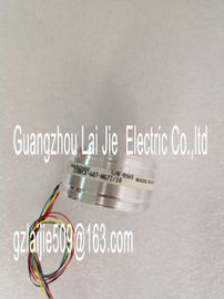
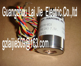
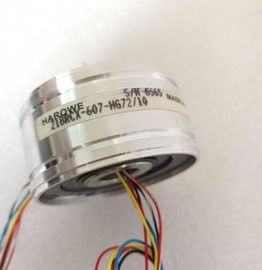
| Place of Origin: | GERMANY |
| Brand Name: | HAROWE |
| Certification: | CE |
| Model Number: | 21BRCX-331-F45 |
| Minimum Order Quantity: | 1pcs |
|---|---|
| Packaging Details: | carton |
| Delivery Time: | in stock |
| Payment Terms: | T/T, Western Union, MoneyGram |
| Supply Ability: | 100pcs/week |
| HAROWE: | HAROWE | 21BRCX-331-F45: | 21BRCX-331-F45 |
|---|---|---|---|
| GERMANY: | GERMANY | Temperature: | 20-90 |
| Dimension: | 90mm | Wire: | Wire |
| Color: | Black |
| GSD file in STEP 7 (TIA Portal) V12 or higher |
|
| or STEP 7 V5.5 SP3 or higher |
|
| Firmware update V1.0.0 or higher V13 or higher with HSP 0102 |
Calibration in runtime V1.0.0 or higher V13 or higher with
HSP 0102
X
Identification data I&M0 to I&M3 V1.0.0 or higher V13 or higher with
HSP 0102
X
Parameter assignment in RUN V1.0.0 or higher V13 or higher with
HSP 0102
X
Module internal shared input (MSI) V1.0.0 or higher V13 Update 3 or
higher
(PROFINET IO only)
X
(PROFINET IO only)
Configurable submodules / submodules for
Shared Device
V1.0.0 or higher V13 Update 3 or
higher
(PROFINET IO only)
X
(PROFINET IO only)
You can configure the module with STEP 7 (TIA Portal) and with a GSD file.The following accessories are supplied with the module and can also be ordered separately
as spare parts:
● Front connector (push-in terminals) including cable tie
● Shield bracket
● Shield terminal
● Power supply element (push-in terminals)
● Labeling strips
● U connector
● Universal front door
For more information on accessories, refer to the system manual AutomatioThis section contains the block diagram of the module and outlines various connection
options.
For more information on front connector wiring and creating cable shields, etc., refer to the
"Wiring" section in the Automation System record in the section Structure of a data record for dynamic reference temperature
(Page 59).
Note
You may use and combine the different wiring options for all channels.Voltage input channel n (voltage only)
Mn+/Mn- Measuring input channel n
In+/In- Current input channel n (current only)
Ic n+/Ic n- Current output for RTD, channel n
UVn Supply voltage at channel n for 2-wire transmitters (2WT)
L+ Connection for supply voltage
M Ground connection
MANA Reference potential of the analog circuit
CHx Channel or display of the channel status
PWR Display for the supply voltaThe power supply element is plugged onto the front connector for powering the analog
module. Wire the supply voltage to terminals 41 (L+) and 43 (M). The example in the following figure shows the pin assignment for current measurement with
4-wire transmittersWiring 4-wire transmitter
② Analog digital converter (ADC)
③ Backplane bus interface
④ Supply voltage via power supply element
⑤ Equipotential bonding cable (optional)
Figure 3-3 Block diagram and pin assignment for current measurementThe example in the following figure shows the pin assignment for current measurement with
2-wire transmitterWiring 2-wire transmitter
② Analog digital converter (ADC)
③ Backplane bus interface
④ Supply voltage via power supply element
⑤ Equipotential bonding cable (optional)
Figure 3-4 Block diagram and pin assignment for current measurement with 2-wire transmitterThe example in the figure below shows the pin assignment for 2-wire connection of
resistance sensors or thermal resistors2-wire connection
Analog digital converter (ADC)
③ Backplane bus interface
④ Supply voltage via power supply element
⑤ Equipotential bonding cable (optional)
Figure 3-5 Block diagram and pin assignment for 2-wire connectionThe example in the figure below shows the pin assignment for 3- and 4-wire connection of
resistance-based sensors or thermal resistors.4-wire connection
② 3-wire connection
③ Analog digital converter (ADC)
④ Backplane bus interface
⑤ Supply voltage via power supply element
⑥ Equipotential bonding cable (optional)
Figure 3-6 Block diagram and pin assignment for 3- and 4-wire connectionThe figure below shows an example of the pin assignment for thermocouples for external or
internal compensation.Wiring of a thermocouple for internal compensation
② Wiring of a thermocouple for external compensation
③ Analog digital converter
④ Backplane bus interface
⑤ Supply voltage via power supply element
⑥ Equipotential bonding cable (optional)
Figure 3-7 Block diagram and pin assignment for the thermocoupleThe following figure shows an example of the pin assignment for grounded thermocouples
for internal compensationWiring of a thermocouple (grounded) for internal compensation
② Analog digital converter (ADC)
③ Backplane bus interface
④ Supply voltage via power supply element
⑤ Equipotential bonding cable (optional)
Figure 3-8 Block diagram and pin assignment for grounded thermocoupleThe module is set to voltage measurement type with measuring range ±10 V by default. You
need to reassign the module parameters with STEP 7 if you want to use a different
measurement type or range.
Deactivate the input if it is not going to be used. The module cycle time is shortened and the
interference factors that lead to failure of the module (for example, triggering a hardware
interrupt) are avoided.
Measurement types and ranges
The following table shows the measurement types and the respective measuring range.
Table 4- 1 Measurement types and rangesThe tables of the input ranges, overflow, underrange, etc.