 |
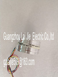
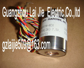
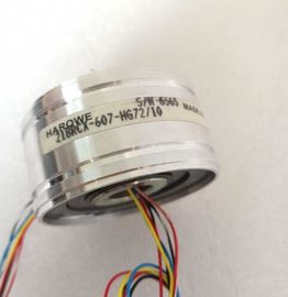
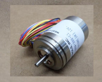
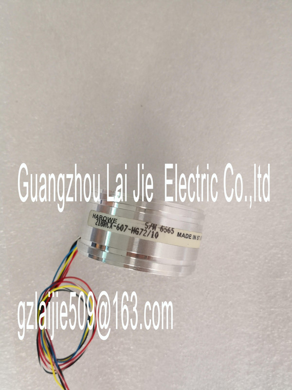
| Place of Origin: | GERMANY |
| Brand Name: | HAROWE |
| Certification: | CE |
| Model Number: | 11BRCX-300-C108/6-01 |
| Minimum Order Quantity: | 1pcs |
|---|---|
| Packaging Details: | carton |
| Delivery Time: | in stock |
| Payment Terms: | T/T, Western Union, MoneyGram |
| Supply Ability: | 100pcs/week |
| HAROWE: | HAROWE | 11BRCX-300-C108/6-01: | 11BRCX-300-C108/6-01 |
|---|---|---|---|
| GERMANY: | GERMANY | Material: | Iron |
| Color: | Black | Temperature: | 20-90 |
| Dimension: | 90mm | Wire: | Wire |
| Abbreviations used Meaning of the abbreviations used in the following figures: |
|
| Un+/Un- Voltage input channel n (voltage only) In+/In- Current input channel n (current only) |
|
| + Supply voltage connection M Ground connection |
Pin assignment for the power supply element
The power supply element is plugged onto the front connector for powering the analog
module. Wire the supply voltage to terminals 41 (L+) and 44 (M). Use terminals 42 (L+) and
43 (M) to loop the potential to the next module.
Figure 3-1 Power supply element wiringThe example in the figure below shows the pin assignment for a voltage measurementAnalog-to-Digital Converter (ADC) CHx Channel or 8 x channel status (green/red)
② Electrical isolation RUN Status display LED (green)
③ Backplane bus interface ERROR Error display LED (red)
④ Supply voltage via power supply element PWR LED for power supply (green)and terminal assignment for 4-wire transducer for current measurement
The example in the following figure shows the pin assignment for current measurement with
4-wire transducersConnector 4-wire transducer CHx Channel or 8 x channel status (green/red)
② Analog-to-Digital Converter (ADC) RUN Status display LED (green)
③ Electrical isolation ERROR Error display LED (red)
④ Backplane bus interface PWR LED for power supply (green)
⑤ Supply voltage via power supply element
⑥ Equipotential bonding cable (optional)
Figure 3-3 Block diagram and terminal assignment for 4-wire transducer for current measurementConnector 2-wire transducer CHx Channel or 8 x channel status
(green/red)
② Analog-to-Digital Converter (ADC) RUN Status display LED (green)
③ Electrical isolation ERROR Error display LED (red)
④ Backplane bus interface PWR LED for power supply (green)
⑤ Supply voltage via power supply element
⑥ Equipotential bonding cable (optional)
Figure 3-4 Block diagram and terminal assignment for 2-wire transducer for current measurementThe module is set to voltage measuring type with measuring range ±10 V by default. You
need to reassign the module parameters with STEP 7 if you want to use a different
measuring type or range.
The following table shows the measuring types and the respective measuring range.
Measurement type Measuring range Representation of analog
values
Voltage 1 V to 5 V
±2.5 V
±5 V
±10 V
See Appendix Representation
of analog
values in voltage
measuring ranges
(Page 62).
Current 2WMT
(2-wire transducer)
4 mA to 20 mA See Appendix Representation
of analog
values in the current
measuring ranges
(Page 63).
Current 4WMT
(4-wire transducer)
4 mA to 20 mA
0 mA to 20 mA
±20 mA
Deactivated -
The tables of the input ranges, overflow, undershoot range, etc. are available in appendix
Representation of analog values (Page 60).The AI 8xU/I HF is usually already integrated in the hardware catalog of STEP 7 (TIA Portal).
In this case, STEP 7 (TIA Portal) checks the configured properties for plausibility during
configuration.
However, you can also assign parameters to the module by means of a GSD file and the