|
| Place of Origin: | GERMANY |
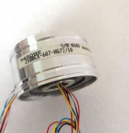
| Brand Name: | HAROWE |
| Certification: | CE |
| Model Number: | 11BRCT-300-P58A |
| Minimum Order Quantity: | 1pcs |
|---|---|
| Packaging Details: | carton |
| Delivery Time: | in stock |
| Payment Terms: | T/T, Western Union, MoneyGram |
| Supply Ability: | 100pcs/week |
| HAROWE: | HAROWE | 11BRCT-300-P58A: | 11BRCT-300-P58A |
|---|---|---|---|
| Material: | Iron | Germany: | Germany |
| Color: | Black | Temperature: | 20-90 |
| Wire: | Wire |
| additional information in the Interrupts section of the manual for the PROFIBUS DP interface module on the he parameters in |
|
| data records 0 to 7 and in data record 8 are available for 1x 8-channel configuration and are assigned as follows: |
|
| Data record 0 for channel 0 ● Data record 1 for channel 1 ● … |
Data record 6 for channel 6
● Data record 7 for channel 7
● Data record 8 for the reference channel (COMP)
For configuration 8 x 1-channel, the module has 8 submodules with one channel each and
one submodule for the reference channel. The parameters for the channel are available in
data record 0 and are assigned as follows:
● Data record 0 for channel 0 (submodule 1)
● Data record 0 for channel 1 (submodule 2)
● …
● Data record 0 for channel 6 (submodule 7)
● Data record 0 for channel 7 (submodule 8)
● Data record 0 for the reference channel (COMP) (submodule 9)
Address the respective submodule for data record transfer.vMeasurement type Code
Deactivated 0000 0000
Voltage 0000 0001
Current, 2-wire transmitter 0000 0011
Current, 4-wire transmitter 0000 0010
Resistance, 4-wire connection *) **) 0000 0100
Resistance, 3-wire connection *) **) 0000 0101
Resistance, 2-wire connection *) ***) 0000 0110
Thermal resistor linear, 4-wire connection *) 0000 0111
Thermal resistor linear, 3-wire connection *) 0000 1000
Thermocouple 0000 1010
*) only possible for channels 0, 2, 4 and 6
**) only for the following measuring ranges: 150 Ω, 300 Ω, 600 Ω, 6 kΩ
***) only for measuring range PTC
Special feature for configuration
If you configure one of the following measuring types at one of the channels 0, 2, 4 and 6:
● Resistance, 4-wire connection
● Resistance, 3-wire connection
● Resistance, 2-wire connection
● Thermal resistor linear, 4-wire connection
● Thermal resistor linear, 3-wire connection
then one of the following channels must be disabled.You have configured "Resistance, 4-wire connection" at channel 0; channel 1 must be
disabled. You have configured "Resistance, 2-wire connection" at channel 2; channel 3 must
be disabledThe following table lists all measuring ranges of the analog input module along with their
codes. Enter these codes accordingly at byte 3 of the data record for the corresponding
channel (see the figure Structure of data record 0: Bytes 7 to 27).The following table lists all measuring ranges along with their codes for the reference
channel (COMP). Enter these codes in byte 3 of data record 8 (see figure Structure of data
record 8, reference channel of the module: Bytes 0 to 27).
Table B- 4 Code for the measuring range, reference channel (COMP)The following table lists all temperature coefficients along with their codes for temperature
measurements with the thermal resistors. You need to enter these codes in
● byte 4 of data record 8 (see figure, Structure of data record 8, reference channel of the
module: bytes 0 to 27) and
● byte 4 of data records 0, 2, 4, 6 and 8 (see figure, Structure of data record 0: Bytes 0 to xed reference temperatures
The values that you can set for fixed reference temperatures must be in the valid range of
values. The resolution is a tenth of a degree.
Table B- 6 Valid values for fixed reference temperatures
Temperature unit Decimal Hexadecimal
Celsius (default) -1450 to 1550 FA56H to 60EH
Fahrenheit (default) -2290 to 3110 F70EH to CCCH
Kelvin (default) 1282 to 3276 502H to 10BAH
Hardware interrupt limits
The values that you can set for hardware interrupts (high/low limit) must not violate the
over/underrange of the respective rated measuring range.
The following tables list the valid hardware interrupt limits. The limits depend on the selected
measurement type and measuring range.he WRREC instruction is used to transfer the reference junction temperature via data
record 192 to data record 199 to the module.
The description of the WRREC instruction can be found in the online help from STEP 7.
If you have set the "Dynamic reference temperature" value for the "Reference junction"