|
| Place of Origin: | GERMANY |
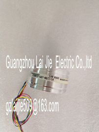
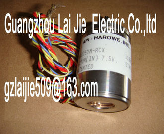
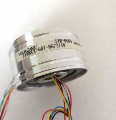
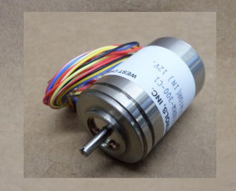
| Brand Name: | HAROWE |
| Certification: | CE |
| Model Number: | 11BRCX-300-G10/5 |
| Minimum Order Quantity: | 1pcs |
|---|---|
| Packaging Details: | carton |
| Delivery Time: | in stock |
| Payment Terms: | T/T, Western Union, MoneyGram |
| Supply Ability: | 100pcs/week |
| HAROWE: | HAROWE | 11BRCX-300-G10/5: | 11BRCX-300-G10/5 |
|---|---|---|---|
| GERMANY: | GERMANY | Material: | Iron |
| Temperature: | 20-90 | Wire: | Wire |
| Dimension: | 90mm |
| Table 5- 5 Diagnostics alarms, their meaning and corrective measures Diagnostics alarm Error code Meaning Remedy |
|
| Table 5- 5 Diagnostics alarms, their meaning and corrective measures Diagnostics alarm Error code Meaning Remedy |
|
| with larger cross-section Wire break between the module and |
sensor
Connect the cable
Channel not connected (open) • Disable diagnostics
• Connect the channel
Overflow 7H Measuring range violated Check the measuring range
Underflow 8H Measuring range violated Check the measuring range
Parameter assignment
error
10H • The module cannot evaluate parameters
for the channel
• Incorrect parameter assignment.
Correct the parameter assignment
Load voltage missing 11H Supply voltage L+ of the module is
missing
Connect supply voltage L+ to module/channelIf you configure the module with value status (QI), the module always checks all errors even
if the respective diagnostics is not enabled. But the module cancels the inspection as soon
as it detects the first error, regardless if the respective diagnostics has been enabled or not.
The result may be that enabled diagnostics may not be displayed.
Example: You have enabled "Underflow" diagnostics, but the module detects the previous
"Wire break" diagnostics and aborts after this error message. The "Underflow" diagnostics is
not detected.
Recommendation: To ensure that all errors are subjected to the diagnostics, select all check
boxes under "Diagnosticsroduct type designation AI 8xU/I HF
Hardware functional status FS01
Firmware version V1.1.0
• FW update possible Yes
Product function
I&M data Yes; I&M0 to I&M3
Measuring range scalable No
Measured values scalable Yes
Measuring range adjustment Yes
Engineering with
STEP 7 TIA Portal can be configured/integrated
V14 / -
STEP 7 can be configured/integrated as of version V5.5 SP3 / -
PROFIBUS as of GSD version/GSD revision V1.0 / V5.1
PROFINET as of GSD version/GSD revision V2.3 / -
Operating mode
Oversampling No
MSI Yes
CiR Configuration in RUN
Configuration in RUN possible Yes
Calibration in RUN possible Yes
Supply voltage
Rated value (DC) 24 V
Valid range, low limit (DC) 20.4 V
Valid range, high limit (DC) 28.8 V
Reverse polarity protection Yes
Input current
Current consumption, max. 50 mA; with 24 V DC supply
Power
Power consumption from the backplane bus 0.85 W
Power loss
Power loss, typ• For current measurement 8
• For voltage measurement 8
Permissible input voltage for voltage input (destruction
limit), max.
28.8 V
Permissible input current for current input (destruction
limit), max.
40 mA
Input ranges (rated values), voltages
1 V to 5 V Yes
Input resistance (1 V to 5 V) 100 kΩ
-10 V to +10 V Yes
Input resistance (-10 V to +10 V) 100 kΩ
-2.5 to +2.5 V Yes
Input resistance (-2.5 to +2.5 V) 100 kΩ
5 V to +5 V Yes
Input resistance (-5 V to +5 V) 100 kΩ
Input ranges (rated values), currents
0 mA to 20 mA Yes
Input resistance (0 mA to 20 mA) 25 Ω; plus approx. 42 ohm for overvoltage protection
by PTC
-20 mA to +20 mA Yes
Input resistance (-20 mA to +20 mA) 25 Ω; plus approx. 42 ohm for overvoltage protection
by PTC
4 mA to 20 mA Yes
Input resistance (4 mA to 20 mA) 25 Ω; plus approx. 42 ohm for overvoltage protection
by PTC
Cable length
shielded, max. 800 m
Analog value generation for the inputs
Integration and conversion time/resolution per
channeResolution with overrange (bit including sign),
max.
16 bit
Configurable integration time Yes
Integration time (ms) Fast mode: 2.5 / 16.67 / 20 / 100 ms; standard