|
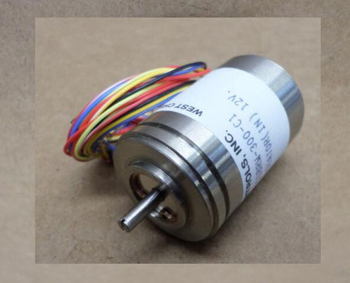
| Place of Origin: | GERMANY |
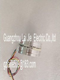
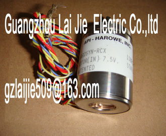
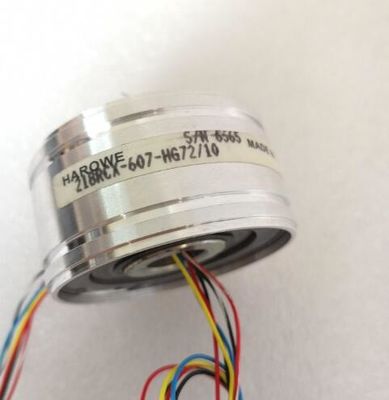
| Brand Name: | HAROWE |
| Certification: | CE |
| Model Number: | 11BRCX-300-F10/10 |
| Minimum Order Quantity: | 1pcs |
|---|---|
| Packaging Details: | carton |
| Delivery Time: | in stock |
| Payment Terms: | T/T, Western Union, MoneyGram |
| Supply Ability: | 1pcs |
| HAROWE: | HAROWE | 11BRCX-300-F10/10: | 11BRCX-300-F10/10 |
|---|---|---|---|
| Material: | Iron | Color: | Black |
| Temperature: | 20-90 | Dimension: | 90mm |
| Germany: | Germany | Wire: | Wire |
| Table 5- 2 PWR status display LED PWR Meaning Remedy |
|
| Off Supply voltage L+ to module too low or missing Check supply voltage L+. |
|
| On Supply voltage L+ is present and OK. --- |
CHx LED
Table 5- 3 CHx status display
LED CHx Meaning Remedy
Off
Channel disabled ---
On
Channel configured and OK. ---
On
Channel is configured (channel error pending).
Diagnostic alarm: e.g. wire break
Check the wiring.
Disable diagnosticsAnalog input module AI 8xU/I HF supports the following diagnostic and hardware interrupts.
You can find detailed information on the event in the error organization block with the
RALRM instruction (read additional interrupt info) and in the STEP 7 online help.
Diagnostic interrupt
The module generates a diagnostic interrupt at the following events:
● Missing supply voltage L+
● Wire break
● Overflow
● Underflow
● Parameter assignment error
Hardware interrupt
The module generates a hardware interrupt at the following events:
● Low limit violated 1
● High limit violated 1
● Low limit violated 2
● Violation of high limit 2
The module channel that triggered the hardware interrupt is entered in the start information
of the organization block. The following figure shows the assignment of the local data double
word 8 by the start information of the hardware interrupt organization block the two high limits 1 and 2 are reached at the same time, the module always signals the
hardware interrupt for high limit 1 first. The configured value for high limit 2 is irrelevant. After
processing the hardware interrupt for high limit 1, the module triggers the hardware interrupt
for high limit 2.
The module has the same reaction when the low limits are reached at the same time. If the
two low limits 1 and 2 are reached at the same time, the module always signals the
hardware interrupt for low limit 1 first. After processing the hardware interrupt for low limit 1,
the module triggers the hardware interrupt for low limit 2.User Structure Identifier)
W#16#0001 Additional interrupt info for hardware interrupts
of the I/O module
2
The channel that triggered the hardware interrupt follows.
Channel B#16#00 to B#16#n Number of the event-triggering channel (n =
number of module channels -1)
1
It follows the error event that triggered the hardware interrupt.
Event B#16#03 Low limit violated 1 1
B#16#04 High limit violated 1
B#16#05 Low limit violated 2
B#16#06 Violation of high limit A diagnostics alarm is generated and the ERROR LED flashes for each diagnostics event on
the module. The diagnostics alarms can be read out in the diagnostics buffer of the CPU, for
example. You can evaluate the error codes with the user program.
If the module is operated distributed with PROFIBUS DP in an ET 200MP system, you have
the option to read out diagnostics data with the instruction RDREC or RD_REC using data
record 0 and 1. The structure of the data records is available on the in the "Manual
for interface module IM 155-5 DP ST (6E155-5BA00-0AB0)".