 |
| Place of Origin: | GERMANY |
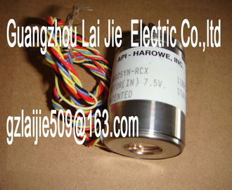
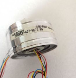
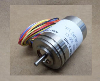
| Brand Name: | HAROWE |
| Certification: | CE |
| Model Number: | 11BRCX-300-C-58 |
| Minimum Order Quantity: | 1pcs |
|---|---|
| Packaging Details: | carton |
| Delivery Time: | in stock |
| Payment Terms: | T/T, Western Union, MoneyGram |
| Supply Ability: | 100pcs/week |
| HAROWE: | HAROWE | 11BRCX-300-C-58: | 11BRCX-300-C-58 |
|---|---|---|---|
| GERMANY: | GERMANY | Material: | Iron |
| Temperature: | 20-90 | Wire: | Wire |
| Dimension: | 90mm | Color: | Black |
| configuration software of any provider. The module does not check the validity of the configured properties until after the configuration has been loaded. |
|
| When you assign the module parameters in STEP 7, you use various parameters to specify the module properties. The following table lists the configurable parameters. The effective |
|
| range of the configurable parameters depends on the type of configuration. The following configurations are possible: |
![]()
![]()
![]()
![]()
| Central operation with a CPU ● Distributed operation on PROFINET IO in an ET 200MP system |
|
| Distributed operation on PROFIBUS DP in an ET 200MP system When assigning parameters in the user program, use the WRREC instruction to transfer the |
|
| Distributed operation on PROFIBUS DP in an ET 200MP system When assigning parameters in the user program, use the WRREC instruction to transfer the |
The following parameter settings for the channels are possible:
Table 4- 1 Configurable parameters and their defaultsMeasuring range adjustment
• Disable
• Enable
Disable Yes Channel Channel
• Measuring range adjustment
high limit (mV
or µA)
Value within the
nominal range of the
measuring range
greater than lower
limit
High limit Yes Channel Channel 4)
• Measuring range adjustment
low limit (mV
or µA)
Value within the
nominal range of the
measuring range
smaller than high
limit
Low limit Yes Channel Channel 4)
• Scaled high nominal
range limit
Scale
• High limit
• Low limit
High limit Yes Channel ---
• Scaled low nominal
range limit
Scale
• High limit
• Low lim) If you enable diagnostics for multiple channels, you will receive an alarm surge on failure of the supply voltage because
each enabled channel will detect this fault.
You can prevent this message burst by assigning the diagnostics function to one channel only.
2) When "Wire break" diagnostics is disabled, the current limit of 1.185 mA applies to the value status. For measured
values below 1.185 mA, the value status is always: 0 = fault.
3) You can set the effective range of the diagnostics for each channel in the user program with data records 0 to 7.
4) You can set the current limit for wire break diagnostics, the "Hardware interrupt" parameter, the "Measuring range adjustment
high and low limit" and the hardware interrupt limits in the user program with data records 0 to 7.Enabling of the diagnostics, with missing or too little supply voltage L+.
Overflow
Enabling of the diagnostics if the measured value violates the high limit.
Underflow
Enabling of the diagnostics if the measured value violates the low limit.
Wire break
Enabling of the diagnostics if the module has no current flow or the current is too weak for
the measurement at the corresponding configured input or the applied voltage is too low.
Current limit for wire break diagnostics
Threshold for reporting wire breaks. The value can be set to 1.185 mA or 3.6 mA, depending
on the sensor used.
Interference frequency suppression
Suppresses the interference affecting analog input modules that is caused by the frequency