|
| Place of Origin: | GERMANY |
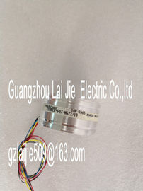
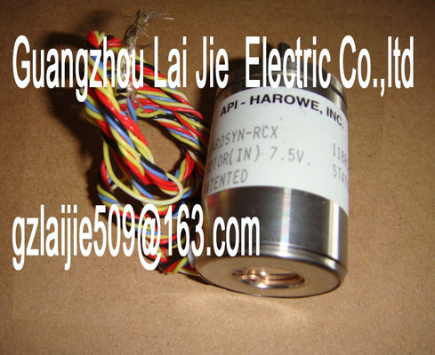
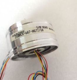
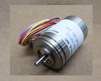
| Brand Name: | HAROWE |
| Certification: | CE |
| Model Number: | 11BRCX300B10A |
| Minimum Order Quantity: | 1pcs |
|---|---|
| Packaging Details: | carton |
| Delivery Time: | in stock |
| Payment Terms: | T/T, Western Union, MoneyGram |
| Supply Ability: | 100pcs/week |
| HAROWE: | HAROWE | 11BRCX300B10A: | 11BRCX300B10A |
|---|---|---|---|
| GERMANY: | GERMANY | Material: | Iron |
| Dimension: | 90mm | Wire: | Wire |
| Temperature: | 20-90 |
| 0 mA to 20 mA 4 mA to 20 mA |
|
| ±20 mA Resistor |
|
| (2-wire connection) PTC Resisto |
(3-wire connection)
(4-wire connection)
150 Ω
300 Ω
600 Ω
6000 ΩThe tables of the input ranges, overflow, underrange, etc. are available in the appendix
Representation of analog values (Page 61).PTC resistors are suitable for temperature monitoring of electrical devices, such as motors,
drives, and transformers.
Use Type A PTC resistors (PTC thermistor) in accordance with DIN/VDE 0660, part 302. In
doing so, follow these steps:
1. Choose "Resistor (2-wire terminal)" and "PTC" in STEP 7.
2. Connect the PTC using 2-wire connection technology.
If you enable the "Underflow" diagnostics in STEP 7, it will be signaled for resistance values
<18 Ω. In this case, this diagnostic signifies "Short-circuit in the wiring".
The figure below shows the address space assignment for AI 4xU/I/RTD/TC ST with PTC
resistorsThe diagram below shows the temperature curve and the associated switching points.If faults occur (for example supply voltage L+ missing) that make it impossible to acquire
measured values with PTC resistors, the corresponding channels (IB x/IB x+1) report
overflow (7FFFH). If the value status (QI) is enabled, the value 0 = fault is output in the
corresponding bithe module properties. The following table lists the configurable parameters. The effective
range of the configurable parameters depends on the type of configuration. The following
configurations are possible:
● Central operation with a CPU
● Distributed operation on PROFINET IO in an ET 200MP system
● Distributed operation on PROFIBUS DP in an ET 200MP system
When assigning parameters in the user program, use the WRREC instruction to transfer the
parameters to the module by means of data records; refer to the section Parameter
assignment and structure of the parameter data records (Page 50).
The following parameter settings are possible:
Table 4- 2 Configurable parameters and their defaults
Parameters Range of values Default
setting
R• Measurement type See section Measurement
types and
ranges (Page 21)
Voltage Yes Channel Channel
• Measuring range ±10 V Yes Channel Channel
• Temperature coefficient Pt: 0.003851
Pt: 0.003902
Pt: 0.003916
Pt: 0.003920
Ni: 0.00618
Ni: 0.00672
LG-Ni: 0.005000
0.003851 Yes Channel Channel
• Temperature unit • Kelvin (K)
• Fahrenheit (°F)
• Celsius (°C)
°C Yes Channel Module
• Interference frequency
suppression
400 Hz
60 Hz
50 Hz
10 Hz
50 Hz Yes Channel Module
• Smoothing None/low/medium/hi
gh
None Yes Channel Channel
• Reference junction • Fixed reference
temperature
• Dynamic reference
temperature
Internal reference
junction
Internal
reference
junction
Yes Channel Module 4)
• Dynamic reference
temperature
• Internal reference
junction
• Fixed reference temperature
Temperature 25 °C Yes Channel --- 4)Hardware interrupt low
limit 1
Yes/No No Yes Channel --- 4)
• Hardware interrupt high
limit 1
Yes/No No Yes Channel --- 4)
• Hardware interrupt low
limit 2
Yes/No No Yes Channel --- 4)
• Hardware interrupt high
limit 2
Yes/No No Yes Channel --- 4)
1) If you enable diagnostics for multiple channels, you will receive an alarm surge on failure of the supply voltage because
each enabled channel will detect this fault. You can prevent this alarm surge by assigning the diagnostics function to
one channel only.
2) When "Wire break" diagnostics is disabled, the current limit of 1.185 mA is applied to the value status. For measured
values below 1.185 mA, the value status is always: 0 = fault.
3) You can set the effective range of the diagnostics for each channel in the user program with data records 0 to 3.
4) You can set the current limit for wire break diagnostics, the setting "Fixed reference temperature" as well as the limits for
hardware interrupts in the user program with data records 0 to 3.Enabling of the diagnostics, with missing or too little supply voltage L+.
Overflow
Enabling of the diagnostics if the measured value violates the high limit.
Underflow
Enabling of the diagnostics when the measured value falls below the underrange or for
voltage measurement ranges of ± 50 mV to ± 2.5 V if the inputs are not connected.