 |
| Place of Origin: | GERMANY |
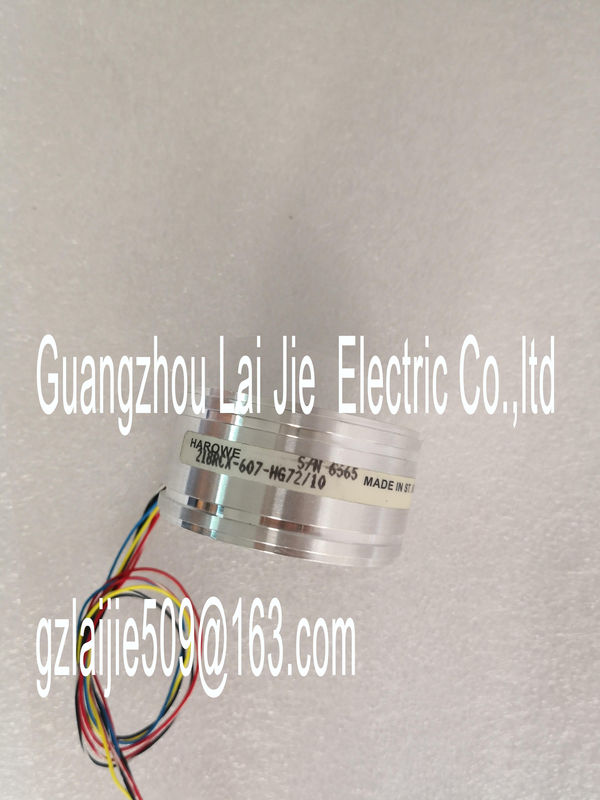
| Brand Name: | HAROWE |
| Certification: | CE |
| Model Number: | 11BRCX-300-B10A |
| Minimum Order Quantity: | 1pcs |
|---|---|
| Packaging Details: | carton |
| Delivery Time: | in stock |
| Payment Terms: | T/T, Western Union, MoneyGram |
| Supply Ability: | 100pcs/week |
| HAROWE: | HAROWE | 11BRCX-300-B10A: | 11BRCX-300-B10A |
|---|---|---|---|
| Material: | Iron | Germany: | Germany |
| Temperature: | 20-90 | Color: | Black |
| Dimension: | 90mm | Wire: | Wire |
| Common mode error Enabling of diagnostics if the valid common mode voltage is exceeded. |
|
| Enable the Common mode error diagnostics when 2WMT is connected, for example, to | |
| check for a short circuit to groundANA or a wire break. If you do not need the Common mode error diagnostics, disable the parameter |
check for a short circuit to groundANA or a wire break. If you do not need the Common mode
error diagnostics, disable the parameter
Reference junction
Enabling of the diagnostics reference junction when the TC channel has no reference
temperature or incorrect reference temperature.
Wire break
Enabling of the diagnostics if the module has no current flow or the current is too weak for
the measurement at the corresponding configured input or the applied voltage is too low.The temperature coefficient depends on the chemical composition of the material. In Europe,
only one value is used per sensor type (default value).
The temperature coefficient (α value) indicates by how much the resistance of a specific
material changes relatively if the temperature increases by 1 °C.
The further values facilitate a sensor-specific setting of the temperature coefficient and
enhance accuracyAt analog input modules, this suppresses interference caused by the frequency of AC mains.
The frequency of AC network may corrupt measurements, particularly in the low voltage
ranges, and when thermocouples are being used. For this parameter, the user defines the
mains frequency prevailing on his system.
Smoothing
The individual measured values are smoothed using filtering. The smoothing can be set in 4
levels.
Smoothing time = number of module cycles (k) x cycle time of the module.
The following figure shows the number of module cycles after which the smoothed analog
value is almost 100%, depending on the set smoothing. It is valid for each signal change at
the analog input.
The following settings can be configured for the reference junction parameter:
Table 4- 3 Possible parameter assignments for the reference junction parameter TC
Setting Description
Fixed reference temperature The reference junction temperature is configured and stored in the module as
a fixed value.
Dynamic reference temperature The reference junction temperature is transferred in the user program from the
CPU to the module by data records 192 to 195 using the WRREC (SFB 53)
instruction.
Internal reference junction The reference junction temperature is determined using an integrated sensor
of the module.
Hardware interrupt 1 or 2
Enabling of a hardware interrupt at violation of high limit 1 or 2 or low limit 1 or 2.Specifies the low limit threshold that triggers hardware interrupt 1 or 2.
High limit 1 or 2
Specifies the high limit threshold that triggers hardware interrupt 1 or 2.The module can be configured in various ways in STEP 7. Depending on the configuration,
additional/different addresses are assigned in the process image of the inputs.
Configuration options of AI 4xU/I/RTD/TC ST
You can configure the module with STEP 7 (TIA Portal) or with a GSD file.
When you configure the module by means of the GSD file, the configurations are available
under different abbreviations/module names.
The following configurations are possible:The value status is always activated for the following module names:
● AI 4xU/I/RTD/TC ST QI
● AI 4xU/I/RTD/TC ST S QI
● AI 4xU/I/RTD/TC ST MSI
An additional bit is assigned to each channel for the value status. The value status bit
indicates if the read in digital value is valid. (0 = value is incorrect). The figure below shows the address space assignment for configuration as a 1 x 4-channel
module. You can freely assign the start address for the module. The addresses of the
channels are derived from the start address.
"IBx" represents the module start address input byte x. Address space for configuration as 1 x 4-channel AI 4xU/I/RTD/TC ST QI with value
statusThe channels of the module are divided up into several submodules with configuration as 4 x
1-channel module. The submodules can be assigned to different IO controllers when the
module is used in a shared device.
The number of available submodules depends on the used interface module. Note the
comments in the respective interface module product manual.
Unlike the 1 x 4-channel module configuration, each of the four submodules has a freely
assignable start address Address space for configuration as 4 x 1-channel AI 4xU/I/RTD/TC ST S QI with value
statusThe channels 0 to 3 of the module are copied in up to 4 submodules with configuration 1 x 4-
channel module (Module-internal shared input, MSI). Channels 0 to 3 are then available with
identical input values in different submodules. These submodules can be assigned to up to
four IO controllers when the module is used in a shared device. Each IO controller has read
access to the same channels.
The number of available submodules depends on the used interface module. Note the
comments in the respective interface module product manual.
Value status (Quality Information, QI)
The meaning of the value status depends on the submodule on which it occurs.
For the first submodule (=base submodule), the value status 0 indicates that the value is
incorrect.
For the 2nd to 4th submodule (=MSI submodule), the value status 0 indicates that the value
is incorrect or the base submodule has not yet been configured (not ready).
The figure below shows the assignment of the address space with submodules 1 and 2.The following figure shows the assignment of the address space with submodule 3 and 4Address space for configuration as 1 x 4-channel AI 4xU/I/RTD/TC ST MSI with value
statusThe figure below shows the LED displays (status and error displays)
of AI 4xU/I/RTD/TC ST.The following tables explain the meaning of the status and error displays. Corrective
measures for diagnostics alarms can be found in the section Diagnostics alarms (Page