 |
| Place of Origin: | GERMANY |
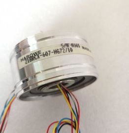
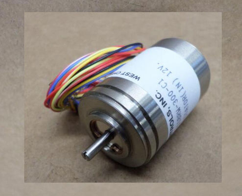
| Brand Name: | HAROWE |
| Certification: | CE |
| Model Number: | 11BRW-30011BRW-300-B95-02 |
| Minimum Order Quantity: | 1pcs |
|---|---|
| Packaging Details: | carton |
| Delivery Time: | in stock |
| Payment Terms: | T/T, Western Union, MoneyGram |
| Supply Ability: | 100pcs/week |
| HAROWRE: | HAROWE | 11BRW-30011BRW-300-B95-02: | 11BRW-30011BRW-300-B95-02 |
|---|---|---|---|
| Material: | Iron | Color: | Black |
| Temperature: | 20-90 | Germany: | Germany |
| Dimension: | 90mm | Wire: | Wire |
| thermometer (RTD) at the reference channel.Wiring of a thermocouple (non-grounded) for internal compensation | |
| CHx Channel or 9 x channel status (green/red) |
|
| Wiring of a thermocouple (non-grounded) for external compensation RUN Status display LED (green) |
Analog-to-Digital Converter (ADC) ERROR Error display LED (red)
④ Electrical isolation PWR LED for power supply (green)
⑤ Backplane bus interface
⑥ Supply voltage via power supply element
⑦ Backplane bus interface potential bonding cable (optional)
Figure 3-4 Block diagram and pin assignment for non-grounded thermocouples and resistance thermometerThe following figure shows an example of the pin assignment for grounded thermocouples
for internal compensation.Wiring of a thermocouple (grounded) for internal compensation
CHx Channel or 9 x channel status
(green/red)
② Analog-to-Digital Converter (ADC) RUN Status display LED (green)
③ Electrical isolation ERROR Error display LED (red)
④ Backplane bus interface PWR LED for power supply (green)
⑤ Supply voltage via power supply element
⑥ Equipotential bonding cable (optional)
Figure 3-5 Block diagram and pin assignment for grounded thermocouplesThe module has a default measurement type resistance thermometer RTD (4-wire
connection) and the measuring range Pt100 Standard. You need to reassign the module
parameters with STEP 7 if you want to use a different measurement type or range.
You use temperature coefficients to determine the measuring ranges for resistance
thermometers / thermocouples according to the GOST standard. You can find the adjustable
temperature coefficients in the Parameter assignment and structure of the parameter data
records (Page 56) section in the table Coding for temperature coefficient.
You can find the analog values for the usable resistance thermometer / thermocouples in the
sections Analog value representation for resistance-type transmitters / resistance
thermometers (Page 74) and Representation of analog values for thermocouples (Page 80).
The following table shows the measuring tyThe tables of the input ranges, overflow, undershoot range, etc. are available in appendix
Representation of analog values (Page 71).PTC resistors are suitable for temperature monitoring of electrical devices, such as motors,
drives, and transformers.
Use Type A PTC resistors (PTC thermistor) in accordance with DIN/VDE 0660, part 302. In
doing so, follow these steps:
1. Select "Resistor 2-wire terminal" and "PTC" in STEP 7.
2. Connect the PTC using 2-wire connection technology.
If you enable the "Underflow" diagnostics in STEP 7, it will be signaled for resistance values
<18 Ω. In this case, this diagnostic signifies "Short-circuit in the wiring".
The following figure shows the address space assignment for the AI 8xU/R/RTD/TC HF
module with PTC resistorsIf faults occur (for example supply voltage L+ missing) that make it impossible to acquire
measured values with PTC resistors, the corresponding channels (IB x/IB x+1) report
overflow (7FFFH). If the value status (QI) is enabled, the value 0 = fault is output in the
corresponding bit.
4.2 Parameters
Parameters of AI 8xU/R/RTD/TC HF
The AI 8xU/R/RTD/TC HF is usually already integrated in the hardware catalog of STEP 7
(TIA Portal). In this case, STEP 7 (TIA Portal) checks the configured properties for
plausibility during configuration.
However, you can also assign parameters to the module by means of a GSD file and the
configuration software of any provider. The module does not check the validity of the
configured properties until after the configuration has been loaded.
When you assign the module parameters in STEP 7, you use various parameters to specify
the module properties. The following table lists the configurable parameters. The effective
range of the configurable parameters depends on the type of configuration. The following
configurations are possible:
● Central operation with a CPU
● Distributed operation on PROFINET IO in an ET 200MP system
● Distributed operation on PROFIBUS DP in an ET 200MP system
When assigning parameters in the user program, use the WRREC instruction to transfer the
parameters to the module by means of data records; refer to the sectFixed reference
temperature
• Dynamic reference