|
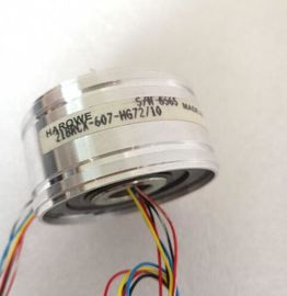
| Place of Origin: | GERMANY |
| Brand Name: | HAROWE |
| Certification: | CE |
| Model Number: | 11BRW-300-B-1 |
| Minimum Order Quantity: | 1pcs |
|---|---|
| Packaging Details: | carton |
| Delivery Time: | in stock |
| Payment Terms: | T/T, Western Union, MoneyGram |
| Supply Ability: | 100pcs/week |
| HAROWE: | HAROWE | 11BRW-300-B-1: | 11BRW-300-B-1 |
|---|---|---|---|
| GERMANY: | GERMANY | COLOR: | BLACK |
| Material: | Iron | Temperature: | 20-90 |
| Dimension: | 90mm | Wire: | Wire |
| Reference channel of the module nal range of the |
|
| measuring rangeIf you enable diagnostics for multiple channels, you will receive an alarm surge on failure of the supply voltage because | |
| each enabled channel will detect this fault. You can prevent this message burst by assigning the diagnostics function to one channel only. |
You can set the effective range of the diagnostics for each channel in the user program with data records 0 to 8.
3) The setting is only possible for channels 0 to 7. If you use the "Reference channel of the module" setting for at least one
channel, you need to operate channel 8 with the resistance thermometer RTD measurement type.
4) You can configure the "Fixed reference temperature" setting and the limits for hardware interrupts in the user program
with data records 0 to 8.Enabling of the diagnostics if the measured value violates the high limit.
Underflow
Enabling of the diagnostics when the measured value falls below the underrange or for
voltage measurement ranges of ± 25 mV to ± 1.0 V if the inputs are not connected.
Reference channel error
● Enable diagnostics for an error at the temperature compensation channel, e.g. wire
break.
● Dynamic reference temperature compensation type is configured and no reference
temperature has been transferred to the module yet.
Wire break
Enable for diagnostics to check the cable resistances.
Temperature coefficient
The temperature coefficient depends on the chemical composition of the material. In Europe,
only one value is used per sensor type (default value).
The temperature coefficient (α value) indicates by how much the resistance of a specific
material changes relatively if the temperature increases by 1 °C.
The further values facilitate a sensor-specific setting of the temperature coefficient and
enhance accuracySuppresses the interference affecting analog input modules that is caused by the frequency
of the AC voltage network used.
The frequency of the AC voltage network can negatively affect the measured value, in
particular when measuring in low voltage ranges and with thermocouples. With this
parameter, the user specifies the line frequency that is predominant in the plant.The individual measured values are smoothed using filtering. The smoothing can be set in 4
levels.
Smoothing time = number of module cycles (k) x cycle time of the module.
The following figure shows after how many module cycles the smoothed analog value is
almost 100%, depending on the set smoothing. Is valid for each signal change at the analog
input.The reference junction temperature is configured and stored in the module as
a fixed value.
Dynamic reference temperature The reference junction temperature is transferred in the user program from the
CPU to the module by data records 192 to 200 using the WRREC (SFB 53)
instruction.
Internal reference junction The reference junction temperature is determined using an integrated sensor
of the module.
Reference channel of the module The reference junction temperature is determined using an external resistance
thermometer (RTD) at the reference channel (CH8) of the module. Enable a hardware interrupt at