|
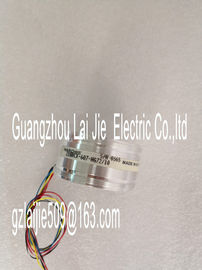
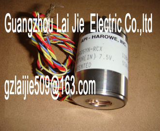
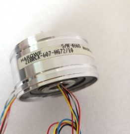
| Place of Origin: | GERMANY |
| Brand Name: | HAROWE |
| Certification: | CE |
| Model Number: | 11BRCX-300-C10/6 |
| Minimum Order Quantity: | 1pcs |
|---|---|
| Packaging Details: | carton |
| Delivery Time: | in stock |
| Payment Terms: | T/T, Western Union, MoneyGram |
| Supply Ability: | 100pcs/week |
| HAROWE: | HAROWE | 11BRCX-300-C10/6: | 11BRCX-300-C10/6 |
|---|---|---|---|
| GERMANY: | GERMANY | Material: | Iron |
| Temperature: | 20-90 | Color: | Black |
| Dimension: | 90mm | Wire: | Wire |
| missing Connect supply voltage L+ to module/channel |
|
| Wire break 6H Impedance of encoder circuit too high |
|
| Use a different encoder type or modify the wiring, for example, using cables with |
larger cross-section
Wire break between the module and
sensor
Connect the cable
Channel not connected (open) • Disable diagnostics
• Connect the channel
Overflow 7H Measuring range violated Check the measuring range
Underflow 8H Measuring range violated Check the measuring range
Common mode error 118H Valid common mode voltage exceeded
Causes when a 2WT is connected,
e.g.:
• Wire break
• Galvanic connection to MANA
Check the wiring, e.g. sensor ground
connections, use equipotential cables
Reference channel
error
15H Reference temperature of the reference
junction for the TC channel
being operated with compensation is
invalid.
Check the resistance thermometer. For
the compensation with data record, restore
communication to the module/station.
Channel temporarily
unavailable
1FH User calibration is active.
Channel currently not providing
current/valid values.
Exit user calibration.
Diagnostics alarms with value status (QI)
If you configure the module with value status (QI), the module always checks all errors even
if the respective diagnostics is not enabled. But the module cancels the inspection as soon
as it detects the first error, regardless if the respective diagnostics has been enabled or not.
The result may be that enabled diagnostics may not be displayed.
Example: You have enabled the diagnostics "Underflow", but the module detects the
previous diagnostics "Wire break" and cancels after this error message. The "Underflow"
diagnostics is not detected.
Recommendation: To ensure that all errors get diagnosed, select all check boxes under
"Diagnostics"Hardware version I01
Firmware version V1.0.0
Product function
I&M data Yes; I&M0 to I&M3
Engineering with
STEP 7 TIA Portal can be configured/integrated
as of version
V13 / V13.0.2
STEP 7 can be configured/integrated as of version V5.5 SP3 / -
PROFIBUS as of GSD version/GSD revision V1.0 / V5.1
PROFINET as of GSD version/GSD revision V2.3 / -
Operating mode
MSI Yes
CiR Configuration in RUN
Reconfiguration in RUN possible Yes
Calibration in RUN possible Yes
Supply voltage
Rated value (DC) 24 V
Valid range, low limit (DC) 20.4 V
Valid range, high limit (DC) 28.8 V
Reverse polarity protection Yes
Input current
Current consumption, max. 140 mA; with 24 V DC supply
Encoder supply
24 V encoder supply
Short-circuit protection Yes
Output current, max. 53 mA
Power
Power consumption from backplane bus 0.7 W
Power loss
Power loss, typ.Number of analog inputs 4
Number of analog inputs with current measurement
4
Number of analog inputs for voltage measurement 4
Number of analog inputs for resistance/resistance
thermometer measurement
2
Number of analog inputs with thermocouple
measurement
4
Permissible input voltage for voltage input (destruction
limit), max.
28.8 V
Permissible input current for current input (destruction
limit), max.
40 mA
Technical unit for temperature measurement adjustable
Yes