|
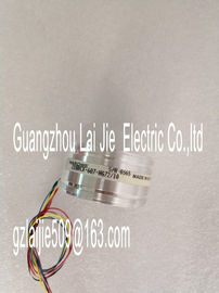
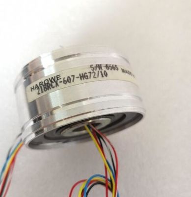
| Place of Origin: | GERMANY |
| Brand Name: | HAROWE |
| Certification: | CE |
| Model Number: | 11BRCX-300-F10/10 |
| Minimum Order Quantity: | 1pcs |
|---|---|
| Packaging Details: | carton |
| Delivery Time: | in stock |
| Payment Terms: | T/T, Western Union, MoneyGram |
| Supply Ability: | 100pcs/week |
| HAROWE: | HAROWE | 11BRCX-300-F10/10: | 11BRCX-300-F10/10 |
|---|---|---|---|
| Material: | Iron | Color: | Black |
| Germany: | Germany | Wire: | Wire |
| Temperature: | 20-90 | Dimension: | 90mm |
| Measurement type resistance (4-wire connection, 3-wire connection, 2-wire connection) |
|
| Configurable for even channels (0 and 2) only. The next odd channel (1 and 3) must be disabled. |
|
| Measurement type thermistor RTD (4-wire connection, 3-wire connection) |
Hardware interrupt limits Only if hardware interrupts are enabled.
Fixed reference temperature Only if the Reference junction parameter and the Fixed reference temperature
value is configured.The module parameters can be assigned in RUN (for example, measuring ranges of
selected channels can be edited in RUN without having an effect on the other channels).
Parameter assignment in RUN
The WRREC instruction is used to transfer the parameters to the module using data records
0 to 3. The parameters set in STEP 7 do not change in the CPU, which means the
parameters set in STEP 7 are still valid after a restart.
The parameters are only checked for plausibility by the module after the transfer to the
moduleIf errors occur during the transfer of parameters with the WRREC instruction, the module
continues operation with the previous parameter assignment. However, a corresponding
error code is written to the STATUS output parameter.
The description of the WRREC instruction and the error codes is available in the STEP 7
online help.
Operation of the module downstream from a PROFIBUS DP interface module
If the module is operated downstream from a IM PROFIBUS DP interface module, the
parameter data records 0 and 1 cannot be read back. You get the diagnostics data records 0
and 1 for the read back parameter data records 0 and 1. You can find more information in
the Interrupts section of the PROFIBUS DP interface module product manual on the For the configuration as a 1 x 4-channel module, the parameters are located in data records
0 to 3 and are assigned as follows:
● Data record 0 for channel 0
● Data record 1 for channel 1
● Data record 2 for channel 2
● Data record 3 for channel 3
For configuration 1 x 4-channel, the module has 4 submodules with one channel each. The
parameters for the channel are available in data record 0 and are assigned as follows:
● Data record 0 for channel 0 (submodule 1)
● Data record 0 for channel 1 (submodule 2)
● Data record 0 for channel 2 (submodule 3)
● Data record 0 for channel 3 (submodule 4)
Address the respective submodule for data record transfer.The example in the following figure shows the structure of data record 0 for channel 0. The
structure of channels 1 to 3 is identical. The values in byte 0 and byte 1 are fixed and may
not be changed.
Enable a parameter by setting the corresponding bit to "1".The following table lists all measurement types of the analog input module along with their
codes. Enter these codes at byte 2 of the data record for the corresponding channel (see the
figure Structure of data record 0: Bytes 7 to 27).
Table B- 2 Code for the measurement typeDisabled 0000 0000
Voltage 0000 0001
Current, 2-wire transmitter 0000 0011
Current, 4-wire transmitter 0000 0010
Resistance, 4-wire connection *) **) 0000 0100