 |
| Place of Origin: | GERMANY |
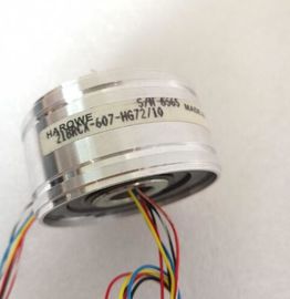
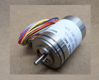
| Brand Name: | HAROWE |
| Certification: | CE |
| Model Number: | 11BRCX-300-J-95C-01 |
| Minimum Order Quantity: | 1pcs |
|---|---|
| Packaging Details: | carton |
| Delivery Time: | in stock |
| Payment Terms: | T/T, Western Union, MoneyGram |
| Supply Ability: | 100pcs/week |
| HAROWE: | HAROWE | 11BRCX-300-J-95C-01: | 11BRCX-300-J-95C-01 |
|---|---|---|---|
| Temperature: | 20-90 | Color: | Black |
| Dimension: | 90mm | Wire: | Wire |
| Germany: | Germany | Material: | Iron |
| hardware catalog of STEP 7 (TIA Portal). In this case, STEP 7 (TIA Portal) checks the configured properties for plausibility during configuration. |
|
| However, you can also assign parameters to the module by means of a GSD file and the | |
| configuration software of any provider. The module does not check the validity of the |
configured properties until after the configuration has been loaded.
When you assign the module parameters in STEP 7, you use various parameters to specify
the module properties. The following table lists the configurable parameters. The effective
range of the configurable parameters depends on the type of configuration. The following
configurations are possible:
● Central operation with a CPU
● Distributed operation on PROFINET IO in an ET 200MP system● Central operation with a CPU
● Distributed operation on PROFINET IO in an ET 200MP system
● Distributed operation on PROFIBUS DP in an ET 200MP system
When assigning parameters in the user program, use the WRREC instruction to transfer the
parameters to the module by means of data records; refer to chapter Parameter assignment
and structure of the parameter data records (Page 42)Voltage/current Voltage Yes Channel Channel
• Output range See chapter
output ranges
(Page 18)
±10 V Yes Channel Channel
• Reaction to CPU STOP • Turn off
• Keep last
value
• Output substitute
value
4)
Turn off Yes Channel Channel 3)
• Turn off
• Keep last
value
• Substitute value See Parameter
assignment and
structure of the
parameter data
records
(Page 42)
0 Yes Channel --- 3)
1) If you enable diagnostics for multiple channels, you will receive an alarm surge on failure of the supply voltage because
each enabled channel will detect this fault.
You can prevent this message burst by assigning the diagnostics function to one channel only.
2) You can set the effective range of the diagnostics for each channel in the user program with data records 64 to 71.
3) You can configure the setting "Output substitute value" and the substitute value in the user program by means of data
records 64 to 71.
Short-circuit detection
The diagnostics for short circuit to ground can be configured for the voltage output type. A
short-circuit detection is not possible for small output values; the output voltages must
therefore be below -0.5 V or above +0.5 V.The diagnostics for short circuit to ground can be configured for the voltage output type. A
short-circuit detection is not possible for small output values; the output voltages must
therefore be below -0.5 V or above +0.5 V.
Open-circuit detection
The diagnostics for open circuit can be configured for the current output type. An open-circuit
detection is not possible for small output values; the output voltages must therefore be below
-3 mA or above +3 mSpecifies the number of sub-cycles per isochronous data cycle for the for the oversampling
function.
Missing supply voltage L+
Enabling of the diagnostics, with missing or too little supply voltage L+.
Wire break
Enabling of the diagnostics if the line to the actuator is broken.
Short circuit to ground
Enabling of the diagnostics if a short-circuit of the output to MANA occurs.
Overflow
Enabling of the diagnostics when the output value exceeds the overrange.
Underflow
Enabling of the diagnostics when the output value violates the underrange.
Reaction to CPU STOP
Determines the reaction of the output to the CPU going into STOP state.
Substitute value
The substitute value is the value that the module outputs in case of a CPU STOPThe module can be configured differently in STEP 7; see following table. Depending on the
configuration, additional/different addresses are assigned in the process image of the
outputs/inputs.
Configuration options of AQ 8xU/I HS
You can configure the module with STEP 7 (TIA Portal) or with a GSD file.
When you configure the module by means of the GSD file, the configurations are available
under different abbreviations/module names.