|
| Place of Origin: | GERMANY |
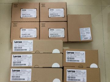
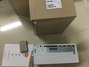
| Brand Name: | LENZE |
| Certification: | CE |
| Model Number: | EVS9331-ET |
| Minimum Order Quantity: | 1pcs |
|---|---|
| Packaging Details: | carton |
| Delivery Time: | in stock |
| Payment Terms: | T/T, Western Union, MoneyGram |
| Supply Ability: | 100pcs/week |
| LENZE: | LENZE | EVS9331-ET: | EVS9331-ET |
|---|---|---|---|
| GERMANY: | GERMANY | Material: | Iron |
| Color: | Black | Temperature: | 20-90 |
| Dimension: | 90mm | Wire: | Wire |
| complete documentation on the SIMATIC automation system and the ET 200MP distributed I/O system gathered together in on |
|
| You can find the Manual Collection on the The comparison list contains an overview of which instructions and functions you can use for | |
| which controller families. You can find the comparison list on the In the CAx data area in "mySupport", you can access the current product data for your CAx |
or CAe system.
You configure your own download package with a few clicks.
In doing so you can select:
● Product images, 2D dimension drawings, 3D models, internal circuit diagrams, EPLAN
macro files
● Manuals, characteristics, operating manuals, certificates
● Product master data
You can find "mySupport" - CAx data on the With the TIA Selection Tool, you can select, configure and order devices for Totally
Integrated Automation (TIA).
This tool is the successor of the SIMATIC Selection Tool and combines the known
configurators for automation technology into one tool.
With the TIA Selection Tool, you can generate a complete order list from your product
selection or product configuration.
You can find the TIA Selection Tool on the You can use the SIMATIC Automation Tool to run commissioning and maintenance activities
simultaneously on various SIMATIC S7 stations as a bulk operation independently of the
TIA Portal.
The SIMATIC Automation Tool provides a multitude of functions:
● Scanning of a PROFINET/Ethernet network and identification of all connected CPUs
● Address assignment (IP, subnet, gateway) and station name (PROFINET device) to a
CPU
● Transfer of the date and the programming device/PC time converted to UTC time to the
module
● Program download to CPU
● Operating mode switchover RUN/STOP
● Localization of the CPU by means of LED flashing
● Reading out CPU error information
● Reading the CPU diagnostic buffer
● Reset to factory settings
● Updating the firmware of the CPU and connected modulesWith PRONETA (PROFINET network analysis), you analyze the PROFINET
network during commissioning. PRONETA features two core functions:
● The topology overview independently scans PROFINET and all connected components.
● The IO check is a fast test of the wiring and the module configuration of a system.
You can find PRONETA on the The module has the following technical properties:
● 16 digital inputs; electrically isolated in groups of 4
● Rated input voltage 120/230 V AC
● Suitable for switches and 2-/3-/4-wire AC proximity switches (alternating voltage)Firmware update V1.0.0 or higher V12 or higher X
Identification data I&M0 to I&M3 V1.0.0 or higher V12 or higher X
Module-internal Shared Input (MSI) V2.0.0 or higher V13 Update 3 or higher
(PROFINET IO only)
X
(PROFINET IO only)
Configurable submodules / submodules
for Shared Device
V2.0.0 or higher V13 Update 3 or higher
(PROFINET IO only)
X
(PROFINET IO only)
Configurable after interface module
IM 155-5 DP ST
V2.0.0 or higher V13 or higher X
You can configure the module with STEP 7 (TIA Portal) and with a GSD fileThe following accessories are supplied with the module and can also be ordered separately
as spare parts:
● Labeling strips
● U connector
● Universal front door
Other components
The following component can be ordered separately:
Front connectors, including potential jumpers and cable ties
You can find additional information on accessories in the /ET 200MP o not insert the potential jumpers included with the front connector!
Wiring and block diagram
The figure below shows you how to wire the module and the assignment of the channels to
the addresses (input byte a to input byte b).The module can be configured differently in STEP 7; see following table. Depending on the
configuration, additional/different addresses are assigned in the process image of the inputs.
The letters "a to d" are printed on the module - "EB a", for example, stands for module start
address input byte a.
Configuration options of DI 16x230VAC BA
You can configure the module with STEP 7 (TIA Portal) or with a GSD file.