|
| Place of Origin: | GERMANY |
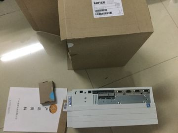
| Brand Name: | LENZE |
| Certification: | CE |
| Model Number: | EVS9332-EPV100 |
| Minimum Order Quantity: | 1pcs |
|---|---|
| Packaging Details: | carton |
| Delivery Time: | in stock |
| Payment Terms: | T/T, Western Union, MoneyGram |
| Supply Ability: | 100pcs/week |
| LENZE: | LENZE | EVS9332-EPV100: | EVS9332-EPV100 |
|---|---|---|---|
| GERMANY: | GERMANY | Material: | Iron |
| Color: | Black | Temperature: | 20-90 |
| Dimension: | 90mm | Wire: | Wire |
| Network optimization thanks to port-specific calculation of the network load ● Increased production availability thanks to online scan and verification of existing systems |
|
| Transparency before commissioning through importing and simulation of existing STEP 7 projects |
|
| Efficiency througThe module has the following technical properties: ● 16 digital outputs, electrically isolated in groups of 8 |
Rated output voltage 24 V DC
● Rated output current 0.5 A per channel
● Configurable substitute values (per channel)
● Configurable diagnostics (per channel)
● Suitable for solenoid valves, DC contactors, and indicator lights
● Switching cycle counter for connected actuators, e.g. solenoid valves
● Hardware compatible with digital output module DQ 16x24VDC/0.5A ST
(6ES7522-1BH00-0AB0).
The module supports the following functions:
Table 2- 1 Version dependencies of the module functions
Function Firmware version
of the module
Configuration software
STEP 7
(TIA Portal) as of V13, SP1
with HSP 0143
GSD file in STEP 7
(TIA Portal) V12 or higher, or
STEP 7 V5.5 SP3 or higher
Firmware update V1.0.0 or higher X --- / X
Identification data I&M0 to I&M3 V1.0.0 or higher X X
Parameter assignment in RUN V1.0.0 or higher X X
Isochronous mode V1.0.0 or higher X ---
Module-internal Shared Output
(MSO)
V1.0.0 or higher X
(PROFINET IO only)
X
(PROFINET IO only)
Configurable submodules / submodules
for Shared Device
V1.0.0 or higher X
(PROFINET IO only)
X
(PROFINET IO only)
Switching cycle counter V1.1.0 or higher as of V15.0 with HSP0247
• PROFINET IO only
• Central operation with a
CPU is supported
X
(PROFINET IO only)
You can configure the module with STEP 7 (TIA Portal) and with a GSD file.
Compatibility
The following table shows the compatibility of the modules and the dependencies between
hardware functional status (FS) and firmware version (FW) used:
Hardware functional status Firmware version Note
FS01 V1.0.0 Upgrade to V1.1.0 not possible
FS02 V1.1.0 Upgrade and downgrade possible between
V1.1.0 and higherThe following accessories are supplied with the module and can also be ordered separately
as spare parts:
● Labeling strips
● U connector
● Universal front cover
Other components
The following component can be ordered separately:
Front connectors, including potential jumpers and cable ties
You can find additional information on accessories in the system manual /ET 200MP Recording the number of switching cycles of the connected devices, e.g. solenoid valves
or load contactors
● Predictive maintenance
Advantages
● You configure this function instead of programming.
● "Monitoring" of each individual channel is possible. You can select which outputs are
"monitored".
● You can adapt the plant configuration flexibly and individually.
● Easy to service and maintain. You can enable and disable the switching cycle counter via
the user program.
● Increase in plant availability. You can schedule actuator replacement in advance for the
next maintenance cycle.
Requirement
Firmware version as of V1.1.0 of the module.
Configuration
You configure the switching cycle counter with the following parameters:
● Switching cycle counter enabled/disabled
● Trigger maintenance interrupt when the limit is reached
● Set limit for maintenance interruptThe module counts the switching cycles by evaluating the rising edges of an output signal. If
the module detects a rising edge, the switching cycle counter (24-bit) for the respective
channel is incremented. After an overflow of the switching cycle counter, it starts again with
0.
If you activate the "Maintenance switching cycles" parameter, the "Limit warning" of the
maintenance interrupt is triggered when the limit is exceeded. Alternatively, activate the
maintenance interrupt in the parameter data sets starting at DS 64.
The current counter states are stored on the module cyclically (approx. every 20 seconds)
and retentively. The switching cycle counters are reset each time the module is restarted
(power off/on).
You activate the function with the "Switching cycle counter" parameter or in the parameter
data sets starting at DS 64.
You can read the current counter states with data set DS 129. Data set DS 129 contains the
counter status for each channel in UDINT format.
You can read the limits for each channel in UDINT format with data set DS 130.
Data set DS 131 enables you to overwrite the current counter value for each switching cycle
counter.
You can set a limit for each switching cycle counter with the "Switching cycle limit" parameter
or with data set DS 131.This section contains the block diagram of the module and outlines various wiring options.
You can find information on wiring the front connector, establishing a cable shield, etc. in the
system manual /ET 200MPThe example in the following figure shows the terminal assignment and the assignment of
the channels to the addresses (output byte a and output byte b)f you want to supply both load groups with the same potential (non-isolated), use the
potential jumpers supplied with the front connector. This helps you to avoid having to
terminate two wires to one terminal.
Proceed as follows:
1. Connect the 24 V DC supply voltage to terminals 19 and 20.
2. Insert the potential jumpers between terminals
– 9 and 29 (L+)
– 10 and 30 (M)
– 19 and 39 (L+)
– 20 and 40 (M)
3. Insert the jumpers between terminals 29 and 39, as well as 30 and 40.
4. Use the terminals 19 and 20 to distribute the potential to the next module.When you assign the module parameters in STEP 7, you use various parameters to specify