 |
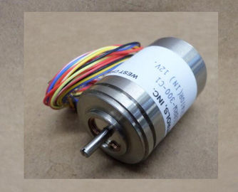
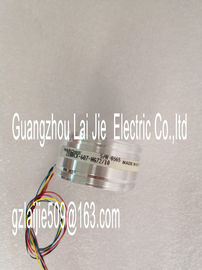
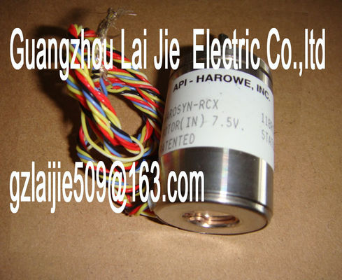
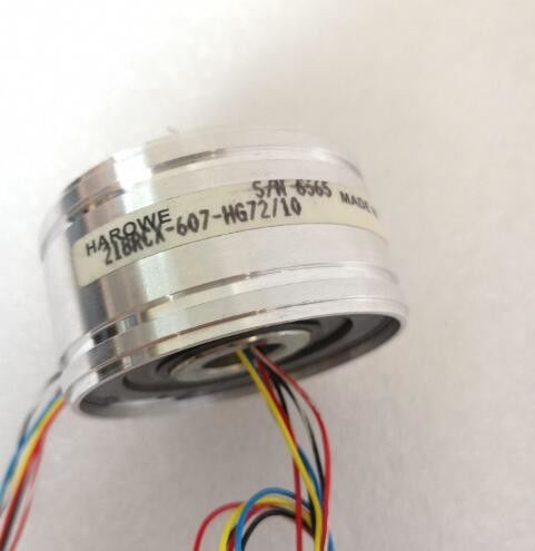
| Place of Origin: | GERMANY |
| Brand Name: | HAROWE |
| Certification: | CE |
| Model Number: | 10BRCX-400-H1/15 |
| Minimum Order Quantity: | 1pcs |
|---|---|
| Packaging Details: | carton |
| Delivery Time: | in stock |
| Payment Terms: | T/T, Western Union, MoneyGram |
| Supply Ability: | 100pcs/week |
| HAROWE: | HAROWE | 10BRCX-400-H1/15: | 10BRCX-400-H1/15 |
|---|---|---|---|
| GERMANY: | GERMANY | Material: | Iron |
| Temperature: | 20-90 | Dimension: | 90mm |
| Wire: | Wire | Color: | Black |
| 19/20 and terminals 39/40. Use the included potential jumpers for this purposeUse the potential | |
| jumpers supplied with the front connector if you want to distribute the 24V | |
| DC supply voltage to a neighboring module. This helps you to avoid having to terminate two wires to one terminal. |
Proceed as follows:
1. Connect the 24 V DC supply voltage to terminals 19 and 20.
2. Insert the potential jumpers between terminals 19 and 39 (L+) and between terminals 20
and 40 (M).
3. Use the terminals 39 and 40 to loop the potential to the next moduleWhen you assign the module parameters in STEP 7, you use various parameters to specify
the module properties. The following table lists the configurable parameters. The effective
range of the configurable parameters depends on the type of configuration. The following
configurations are possible:
● Central operation with a CPU
● Distributed operation on PROFINET IO in an ET 200MP system
● Distributed operation on PROFIBUS DP in an ET 200MP system
For parameter assignment in the user program, the parameters are transferred to the
module using the WRREC instruction (parameter reassignment in RUN) and data records;
see chapter Parameter assignment and structure of the parameter data records (Page 29).
Table 4- 1 Configurable parameters and their defaultsThe module can be configured differently in STEP 7; see following table. Depending on the
configuration, additional/different addresses are assigned in the process image of the
outputs/inputs.
Configuration options of DQ 8x230VAC/5A ST
You can configure the module with STEP 7 (TIA Portal) or with a GSD file.
When you configure the module by means of the GSD file, the configurations are available
under different abbreviations/module names.
The following configurations are possible:1 x 8-channel without value status DQ 8x230VAC/5A ST X X
1 x 8-channel with value status DQ 8x230VAC/5A ST QI X X
1 x 8-channel with value status for module-internal
Shared Output with up to 4
submodules
DQ 8x230VAC/5A ST MSO V13 Update 3 or
higher
(PROFINET IO only)
X
(PROFINET IO onlyThe value status is always activated for the following module names:
● DQ 8x230VAC/5A ST QI
● DQ 8x230VAC/5A ST MSO
An additional bit is assigned to each channel for the value status. The bit for the value status
indicates if the output value specified by the user program is actually pending at the module
terminal (0 = value is incorrect). The following figure shows the assignment of the address space for the configuration as a 8-
channel module with value status. You can freely assign the start address for the module.
The addresses of the channels are derived from the start address.
The letters "a to d" are printed onto the module. "For example, AB a" stands for module start
address output byte a.
For the configuration as a 1 x 8-channel module (module-internal Shared Output, MSO),
channels 0 to 7 of the module are copied to multiple submodules. Channels 0 to 7 are then
available with identical values in various submodules. These submodules can be assigned to
up to four IO controllers when the module is used in a shared device:
● The IO controller to which submodule 1 is assigned has write access to outputs 0 to 7.
● The IO controllers to which submodule 2, 3, or 4 is assigned have read access to outputs
0 to 7.
The number of usable submodules is dependent on the interface module used. Observe the
information in the manual for the particular interface module.
Value status (Quality Information, QI)
The meaning of the value status depends on the submodule on which it occurs.
For the first submodule (=basic submodule), the value status 0 indicates that the value is
incorrect or that the IO controller of the basic submodule is in STOP state.
For the 2nd to 4th submodule (=MSO submodule), the value status 0 indicates that the value
is incorrect or one of the following errors has occurred:
● The basic submodule is not yet configured (not ready).
● The connection between the IO controller and the basic submodule has been interrupted.
● The IO controller of the basic submodule is in STOP or POWER OFF stateThe following figure shows the assignment of the address space for submodules 1, 2, 3, and
4 and the value status.The following tables explain the meaning of the status and error displays. Remedial
measures for diagnostic alarms can be found in section Diagnostic alarms (Page 20Digital output module DQ 8x230VAC/5A ST supports diagnostic interrupts.
Diagnostic interrupt
The module generates a diagnostic interrupt at the following event:
● Missing supply voltage L+
For more information on the error event, refer to the error OB with the "RALRM" instruction
(read additional interrupt info) and to the STEP 7 Online Help.
5.3 Diagnostics alarms