|
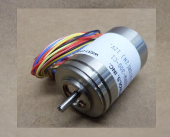
| Place of Origin: | GERMANY |
| Brand Name: | HAROWE |
| Certification: | CE |
| Model Number: | 10BRCX-401-A1/20 |
| Minimum Order Quantity: | 1pcs |
|---|---|
| Packaging Details: | carton |
| Delivery Time: | in stock |
| Payment Terms: | T/T, Western Union, MoneyGram |
| Supply Ability: | 100pcs/week |
| HAROWE: | HAROWE | 10BRCX-401-A1/20: | 10BRCX-401-A1/20 |
|---|---|---|---|
| Matereial: | Iron | Temperature: | 20-90 |
| Color: | Black | Dimension: | 90mm |
| Wire: | Wire | Germany: | Germany |
| Diagnostics alarms A diagnostics alarm is output for each diagnostics event and the ERROR LED flashes on the |
|
| If the module is operated distributed with PROFIBUS DP in an ET 200MP system, you have the option to read out diagnostics data with the instruction RDREC or RD_REC using data |
|
| module. The diagnostics alarms can, for example, be read from the diagnostics buffer of the CPU. You can evaluate the error codes with the user program. |
record 0 and 1. The structure of the data records is available on the in the "Manual
for interface module IM 155-5 DP ST (6E155-5BA00-0AB0With lamp load, max. W; (10,000 switching cycles)
Low energy/fluorescent lamps with electronic
control gear
10 x 58 W (25,000 switching cycles)
Fluorescent tubes, conventionally compensated 1 x 58 W (25,000 switching cycles)
Fluorescent tubes, uncompensated 10 x 58 W (25,000 switching cycles)
Output current
for signal "1" rated value 5 A
for signal "1" permissible range, min. 5 mA; (10 V)
for signal "1" permissible range, max. 8 A; (thermal continuous current)
for signal "0" residual current, max. 0 A
Parallel switching of 2 outputs
For logic operations Yes
For increased performance No
For redundant control of a load Yes
Switching frequency
With resistive load, max. 2 Hz
With inductive load, max. 0.5 Hz
With lamp load, max. 2 Hz
Total current of outputs
Max. current per channel 8 A; (see additional description in the manual)
Max. current per group 8 A; (see additional description in the manual)
Max. current per module 64 A; (see additional description in the manual)
Relay outputs
Number of relay outputs 8
Rated input voltage of relay coil L+ (DC) 24 V
Current consumption of relays (coil current of all
relays), max.
80 mA
External fuse for relay outputs With miniature circuit breaker with characteristic
B for: cos φ 1.0: 600 A
cos Φ 0.5 ... 0.7: 900 A
Diazed fuse 8 A: 1000 A
Contact connection (internal) No
Size of motor starter according to NEMA, max. 5
Number of switching cycles, max. 4000000; (see additional description in the manual)
Relay approved acc. to UL 508 Yes;
250 V AC/5 A g.p.;
120 V AC TV-4 Tungsten; A300, R300
Switching capacity of the contacts
• With inductive load, max. (see additional description in the manual)
• With resistive load, max. (see additional description in the manual)Between the channels Yes; Switching of different phases permitted
Between the channels, in groups of 1
Between the channels and the backplane bus Yes
Between the channels and the load voltage L+ Yes
Permitted potential difference
Between different circuits 75 V DC/60 V AC (basic insulation) between the
backplane bus and the supply voltage L+;
250 V AC between the channels and the supply
voltage L+;
250 V AC between the channels and the backplane
bus;
500 V AC between the channels
Isolation
Isolation tested with between the channels: 2500 V DC;
between the channels and backplane bus:
2500 V DC;
between L+ and backplane bus 707 V DC (Type
Test)The following tables list the permissible number of switching cycles depending on the applied
voltage and current load. Different values apply in each case to resistive and inductive loads.
Table 6- 1 Switching capacity and service life of relay contacts for resistive loadThe dimensional drawing of the module on the mounting rail, as well as a dimensional
drawing with open front cover, are provided in the appendix. Always observe the specified
dimensions for installations in cabinets, control rooms, etc. The data records of the module have an identical structure, regardless of whether you
configure the module with PROFIBUS DP or PROFINET IO.
Dependencies for configuration with GSD file
When a GSD file is used to configure a module, dependencies can arise when "assigning the
parameters".
There are no dependencies for this module. You can assign the individual parameters in any
combination.
Parameter assignment in the user program
You have the option to reconfigure the module in RUN (e.g. the response of selected
channels to the CPU-STOP state can be changed in RUN without having an effect on the
other channels).
Parameter assignment in RUN
The WRREC instruction is used to transfer the parameters to the module using data records
64 to 71. The parameters set in STEP 7 do not change in the CPU, which means the
parameters set in STEP 7 are still valid after a restart.
The parameters are only checked for plausibility by the module after the transferThe module ignores errors that occurred during the transfer of parameters with the WRREC
instruction and continues operation with the previous parameter assignment. However, a
corresponding error code is written to the STATUS output parameter.
The description of the WRREC instruction and the error codes is available in the STEP 7
online help.
Operation of the module behind a PROFIBUS DP interface module
If the module is operated behind a PROFIBUS DP interface module, the parameter data
records 0 and 1 are not read back. You get the diagnostics data records 0 and 1 for the read
back parameter data records 0 and 1. You can find more information in the Interrupts section
of the PROFIBUS DP interface module device manual on the The channel parameters of the module are included in data records 64 to 71 and are
assigned as follows:
● Data record 64 for channel 0
● Data record 65 for channel 1