 |
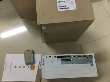
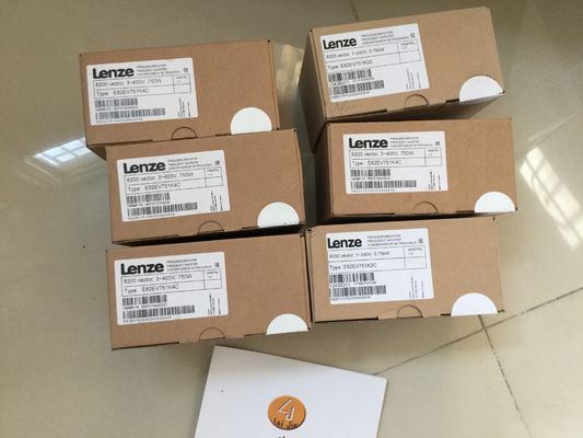
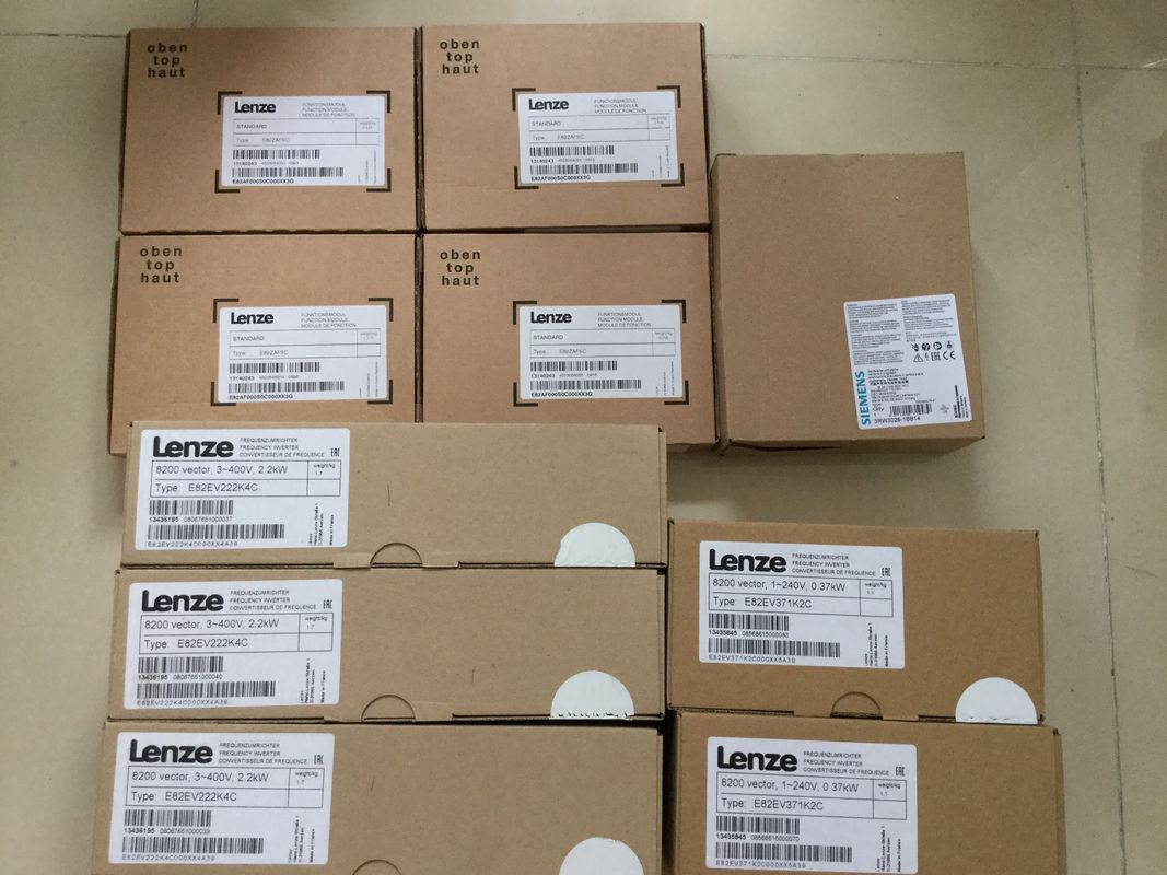
| Place of Origin: | GERMANY |
| Brand Name: | LENZE |
| Certification: | CE |
| Model Number: | EVS9332-ETV100 |
| Minimum Order Quantity: | 1pcs |
|---|---|
| Packaging Details: | carton |
| Delivery Time: | in stock |
| Payment Terms: | T/T, Western Union, MoneyGram |
| Supply Ability: | 100pcs.week |
| LENZE: | LENZE | EVS9332-ETV100: | EVS9332-ETV100 |
|---|---|---|---|
| GERMANY: | GERMANY | Temperature: | 20-90 |
| Wire: | Wire | Dimension: | 90mm |
| Material: | Iron |
| insertedThe dimension drawing of the module on the mounting rail, as well as a dimension drawing with open front cover, are provided in the appendix. Always observe the specified |
|
| imensions for installation in cabinets, control rooms, etcThe WRREC instruction is used to transfer the parameters to the module using data records | |
| 64 to 79. The parameters set in STEP 7 are not changed in the CPU, which means the parameters set in STEP 7 are valid again after a restart. |
The parameters are only checked for plausibility by the module after the transfer.
STATUS output parameter
The module ignores errors that occurred during the transfer of parameters with the WRREC
instruction and continues operation with the previous parameter assignment. However, a
corresponding error code is written to the STATUS output parameter.
The description of the WRREC instruction and the error codes is available in the STEP 7
online help.
Operation of the module behind a PROFIBUS DP interface module
If the module is operated behind a PROFIBUS DP interface module, the parameter data
records 0 and 1 are not read back. You get the diagnostics data records 0 and 1 for the read
back parameter data records 0 and 1. You can find more information in the Interrupts section
of the PROFIBUS DP interface module device manual on the Interne● Data record 64 for channel 0
● Data record 65 for channel 1
● …
● Data record 78 for channel 14
● Data record 79 for channel 15
For the configuration as a 2 x 8-channel module, the module has 2 submodules with eight
channels each. The parameters for the channels are located in data records 64 to 71 and
are assigned as follows:
● Data records 64 to 71 for channels 0 to 7 (submodule 1)
● Data records 64 to 71 for channels 8 to 15 (submodule 2)
Address the respective submodule for data record transfer.
Data record structure
The example in the figure below shows the structure of data record 64 for channel 0. The
structure of channels 1 to 16 is identical. The values in byte 0 and byte 1 are fixed and may
not be changed.
Enable a parameter by setting the corresponding bit to "1".In the product "Digital Modules, Analog Modules, Technological Modules, Communication
Modules and Power Supply Modules of the SIMATIC , ET 200MP", Copyright
AG, 2013 - 2014 (hereinafter "Product"), the following Open Source Software is
used either unchanged or in a form that we have modified, and additionally the other License
Software noted below.
Liability for Open Source Software
Open Source Software is provided free of charge. We are liable for the Product including
Open Source Software contained in accordance with the license conditions applicable to the
Product. Any liability for use of Open Source Software beyond the program flow intended for
the Product is explicitly excluded.
We do not provide any technical support for the Product if it has been modified.Use the potential jumpers supplied with the front connector if you want to distribute the 24 V
DC supply voltage to a neighboring module. This helps you to avoid having to terminate two
wires to one terminal.
Proceed as follows:
1. Connect the 24 V DC supply voltage to terminals 19 and 20.
2. Insert the potential jumpers between terminals 19 and 39 (L+) and between terminals 20
and 40 (M).
3. Use the terminals 39 and 40 to loop the potential to the next module.Ensure that the maximum current load of 8 A per potential jumper is not exceededEnabling of the diagnostics at no or insufficient supply voltage L+.
Reaction to CPU STOP
Determines the reaction of the output to the CPU going into STOP state or when the
connection to the CPU is interrupted.
4.3 Address space
The module can be configured differently in STEP 7; see following table. Depending on the
configuration, additional/different addresses are assigned in the process image output/input.
Configuration options of DQ 16x230VAC/2A ST