 |
| Place of Origin: | GERMANY |
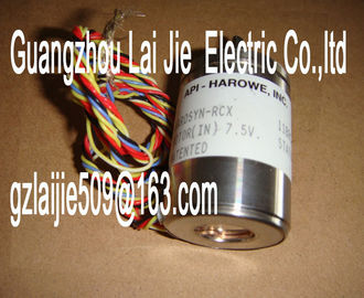
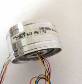
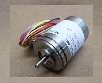
| Brand Name: | HAROWE |
| Certification: | CE |
| Model Number: | 10BRCX-401-A2C/20 |
| Minimum Order Quantity: | 1pcs |
|---|---|
| Packaging Details: | carton |
| Delivery Time: | in stock |
| Payment Terms: | T/T, Western Union, MoneyGram |
| Supply Ability: | 100pcs/week |
| HAROWE: | HAROWE | 10BRCX-401-A2C/20: | 10BRCX-401-A2C/20 |
|---|---|---|---|
| Material: | Iron | Temperature: | 20-90 |
| Dimension: | 90mm | Wire: | Wire |
| Color: | Black | Germany: | Germany |
| Distributed operation on PROFINET IO in an ET 200MP system ● Distributed operation on PROFIBUS DP in an ET 200MP system |
|
| For parameter assignment in the user program, the parameters are transferred to the module using the WRREC instruction (parameter reassignment in RUN) and data records; |
|
| see chapter Parameter assignment and structure of the parameter data records (Page 24). The module can be configured differently in STEP 7; see following table. Depending on the |
configuration, additional/different addresses are assigned in the process image of the
outputs/inputs.
Configuration options of DQ 8x230VAC/2A ST
You can configure the module with STEP 7 (TIA Portal) or with a GSD file.
When you configure the module by means of the GSD file, the configurations are available
under different abbreviations/module names.
The following configurations are possible:The value status is always activated for the DQ 8x230VAC/2A ST MSO module.
An additional bit is assigned to each channel for the value status. The bit for the value status
indicates if the output value specified by the user program is actually pending at the module
terminal (0 = value is incorrect).
Address space for configuration as 8-channel DQ 8x230VAC/2A ST
The following figure shows the assignment of the address space for the configuration as a 8-
channel module with value status. You can freely assign the start address for the module.
The addresses of the channels are derived from the start address.
The letters "a to d" are printed onto the module. "For example, AB a" stands for module start
address output byte a.
Figure 4-1 Address space for configuration as 8-channel DQ 8x230VAC/2A STFor the configuration as a 1 x 8-channel module (module-internal Shared Output, MSO),
channels 0 to 7 of the module are copied to multiple submodules. Channels 0 to 7 are then
available with identical values in various submodules. These submodules can be assigned to
up to four IO controllers when the module is used in a shared device:
● The IO controller to which submodule 1 is assigned has write access to outputs 0 to 7.
● The IO controllers to which submodule 2, 3, or 4 is assigned have read access to outputs
0 to 7.
The number of usable submodules is dependent on the interface module used. Observe the
information in the manual for the particular interface module.
Value status (Quality Information, QI)
The meaning of the value status depends on th
For the first submodule (=basic submodule), the value status 0 indicates that the value is
incorrect or that the IO controller of the basic submodule is in STOP state.
For the 2nd to 4th submodule (=MSO submodule), the value status 0 indicates that the value
is incorrect or one of the following errors has occurred:
● The basic submodule is not yet configured (not ready).
● The connection between the IO controller and the basic submodule has been interrupted.
● The IO controller of the basic submodule is in STOP or POWER OFF stateThe following figure shows the assignment of the address space for submodules 1, 2, 3, and
4 and the value status.Voltage missing or too low at backplane bus • Switch on the CPU and/or the system power
supply modules.
• Verify that the U connectors are inserted.
• Check to see if too many modules are inserted.
Flashes Off
The module starts and flashes until the valid
parameter assignment is set.
---
On Off
Module is configured
Flashes Flashes
Hardware defective Replace the module.0 = Status of the output signal ---
On
1 = Status of the output signaHardware version E01
Firmware version V2.0.0
Product function
I&M data Yes; IM0 to IM3
Engineering with
STEP 7 TIA Portal can be configured/integrated
as of version
V12.0 / V12.0
STEP 7 can be configured/integrated as of version as of V5.5 SP3 / -
Operating mode
MSO Yes
Output voltage
Rated value (AC) 120/230 V AC; 50/60Hz
Power
Power consumption from the backplane bus 0.9 W
Power loss
Power loss, typ. 10.8 W
Digital outputs
Type of digital output Triac
Number of outputs 8
Switching to P potential Yes
Digital outputs, configurable Yes
Short-circuit protection No
Switching capacity of outputs
With resistive load, max. 2 A
With lamp load, max. 50 W
Output voltage
Type of output voltage AC
for signal "1", min. L1 (-1.5 V) at maximum output current;
L1 (-8.5 V) at minimum output currentRUN LED Yes; green LED
ERROR LED Yes; red LED
Monitoring of supply voltage No
Channel status display Yes; green LED
For channel diagnostics No
For module diagnostics Yes; red LED
Electrical isolation
Electrical isolation of channels
Between the channels Yes
Between the channels, in groups of 1
Between the channels and the backplane bus Yes
between the channels and the load voltage LThe following graphs show the loading capacity of the outputs in relation to the mounting
position and the ambient temperature.The data records of the module have an identical structure, regardless of whether you
configure the module with PROFIBUS DP or PROFINET IO.
Dependencies for configuration with GSD file
When a GSD file is used to configure a module, dependencies can arise when "assigning the
parameters".
There are no dependencies for this module. You can assign the individual parameters in any
combination.
Parameter assignment in the user program
You have the option to reconfigure the module in RUN (e.g. the response of selected
channels to the CPU-STOP state can be changed in RUN without having an effect on the
other channels).
Parameter assignment in RUN
The WRREC instruction is used to transfer the parameters to the module using data records
64 to 71. The parameters set in STEP 7 do not change in the CPU, which means the
parameters set in STEP 7 are still valid after a restart.
The parameters are only checked for plausibility by the module after the transfer.
Output parameter STATUS
The module ignores errors that occurred during the transfer of parameters with the WRREC
instruction and continues operation with the previous parameter assignment. However, a
corresponding error code is written to the STATUS output parameter.
The description of the WRREC instruction and the error codes is available in the STEP 7
online help.
Operation of the module behind a PROFIBUS DP interface module
If the module is operated behind a PROFIBUS DP interface module, the parameter data
records 0 and 1 are not read back. You get the diagnostics data records 0 and 1 for the read
back parameter data records 0 and 1. You can find more information in the Interrupts section
of the PROFIBUS DP interface module device manual on the The example in the following figure shows the structure of data record 64 for channel 0. The