|
| Place of Origin: | GERMANY |
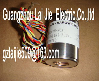
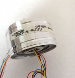
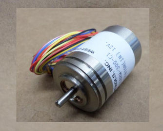
| Brand Name: | HAROWE |
| Certification: | CE |
| Model Number: | 10BRCX-401-B1A/20 |
| Minimum Order Quantity: | 1pcs |
|---|---|
| Packaging Details: | carton |
| Delivery Time: | in stock |
| Payment Terms: | T/T, Western Union, MoneyGram |
| Supply Ability: | 100pcs/week |
| HAROWE: | HAROWE | 10BRCX-401-B1A/20: | 10BRCX-401-B1A/20 |
|---|---|---|---|
| GERMANY: | GERMANY | Material: | Iron |
| Color: | Black | Temperature: | 20-90 |
| Dimension: | 90mm | Wire: | Wire |
| Table 2- 1 Version dependencies of the module functionsThe following components are supplied with the module and can also be ordered separately | |
| as spare parts: ● Labeling strips ● U connector |
|
| Universal front door Other components The following component must be ordered separately: |
Front connectors, including potential jumpers and cable ties
You can find more information on accessories in the Automation System This section contains the block diagram of the module and outlines various connection
options.
For more information on front connector wiring and creating cable shields, for example, refer
to the "Wiring" section in the Automation System Do not insert the potential jumpers included with the front connector!
Abbreviations used
Meaning of the abbreviations used in the following figures:
CHx Channel or display of the channel statusWhen you assign the module parameters in STEP 7, you use various parameters to specify
the module properties. The following table lists the configurable parameters. The effective
range of the configurable parameters depends on the type of configuration. The following
configurations are possible:
● Central operation with a CPU
● Distributed operation on PROFINET IO in an ET 200MP system
● Distributed operation on PROFIBUS DP in an ET 200MP system
For parameter assignment in the user program, the parameters are transferred to the
module using the WRREC instruction (parameter reassignment in RUN) and data records;
see chapter Parameter assignment and structure of the parameter data records (Page 24).
The module can be configured differently in STEP 7; see following table. Depending on the
configuration, additional/different addresses are assigned in the process image of the
outputs/inputs.
Configuration options of DQ 8x230VAC/2A ST
You can configure the module with STEP 7 (TIA Portal) or with a GSD file.
When you configure the module by means of the GSD file, the configurations are available
under different abbreviations/module names.
The following configurations are possible:The value status is always activated for the DQ 8x230VAC/2A ST MSO module.
An additional bit is assigned to each channel for the value status. The bit for the value status
indicates if the output value specified by the user program is actually pending at the module
terminal (0 = value is incorrect).
Address space for configuration as 8-channel DQ 8x230VAC/2A ST
The following figure shows the assignment of the address space for the configuration as a 8-
channel module with value status. You can freely assign the start address for the module.
The addresses of the channels are derived from the start address.
The letters "a to d" are printed onto the module. "For example, AB a" stands for module start
address output byte a.
Figure 4-1 Address space for configuration as 8-channel DQ 8x230VAC/2A STFor the configuration as a 1 x 8-channel module (module-internal Shared Output, MSO),
channels 0 to 7 of the module are copied to multiple submodules. Channels 0 to 7 are then
available with identical values in various submodules. These submodules can be assigned to
up to four IO controllers when the module is used in a shared device:
● The IO controller to which submodule 1 is assigned has write access to outputs 0 to 7.
● The IO controllers to which submodule 2, 3, or 4 is assigned have read access to outputs
0 to 7.
The number of usable submodules is dependent on the interface module used. Observe the
information in the manual for the particular interface module.
Value status (Quality Information, QI)
The meaning of the value status depends on the submodule on which it occurs.
For the first submodule (=basic submodule), the value status 0 indicates that the value is
incorrect or that the IO controller of the basic submodule is in STOP state.
For the 2nd to 4th submodule (=MSO submodule), the value status 0 indicates that the value
is incorrect or one of the following errors has occurred:
● The basic submodule is not yet configured (not ready).
● The connection between the IO controller and the basic submodule has been interrupted.
● The IO controller of the basic submodule is in STOP or POWER OFF stateThe following figure shows the assignment of the address space for submodules 1, 2, 3, and
4 and the value status.Voltage missing or too low at backplane bus ? Switch on the CPU and/or the system power
supply modules.
? Verify that the U connectors are inserted.
? Check to see if too many modules are inserted.
Flashes Off
The module starts and flashes until the valid
parameter assignment is set.
---
On Off
Module is configured
Flashes Flashes
Hardware defective Replace the module.0 = Status of the output signal ---
On
1 = Status of the output signaHardware version E01
Firmware version V2.0.0
Product function
I&M data Yes; IM0 to IM3
Engineering with
STEP 7 TIA Portal can be configured/integrated
as of version
V12.0 / V12.0
STEP 7 can be configured/integrated as of version as of V5.5 SP3 / -
Operating mode
MSO Yes
Output voltage
Rated value (AC) 120/230 V AC; 50/60Hz
Power
Power consumption from the backplane bus 0.9 W
Power loss
Power loss, typ. 10.8 W
Digital outputs
Type of digital output Triac
Number of outputs 8