 |
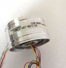
| Place of Origin: | GERMANY |
| Brand Name: | HAROWE |
| Certification: | CE |
| Model Number: | 10BRCX-401-B1P |
| Minimum Order Quantity: | 1pcs |
|---|---|
| Packaging Details: | carton |
| Delivery Time: | in stock |
| Payment Terms: | T/T, Western Union, MoneyGram |
| Supply Ability: | 100pcs/week |
| HAROWE: | HAROWE | 10BRCX-401-B1P: | 10BRCX-401-B1P |
|---|---|---|---|
| GERMANY: | GERMANY | Temperature: | 20-90 |
| Dimension: | 90mm | Color: | Black |
| Wire: | Wire | Material: | Iron |
| Switching to P potential Yes Digital outputs, configurable Yes |
|
| Short-circuit protection No Switching capacity of outputs |
|
| With resistive load, max. 2 A With lamp load, max. 50 W Output voltage |
Type of output voltage AC
for signal "1", min. L1 (-1.5 V) at maximum output current;
L1 (-8.5 V) at minimum output currentRUN LED Yes; green LED
ERROR LED Yes; red LED
Monitoring of supply voltage No
Channel status display Yes; green LED
For channel diagnostics No
For module diagnostics Yes; red LED
Electrical isolation
Electrical isolation of channels
Between the channels Yes
Between the channels, in groups of 1
Between the channels and the backplane bus Yes
between the channels and the load voltage LThe following graphs show the loading capacity of the outputs in relation to the mounting
position and the ambient temperature.The data records of the module have an identical structure, regardless of whether you
configure the module with PROFIBUS DP or PROFINET IO.
Dependencies for configuration with GSD file
When a GSD file is used to configure a module, dependencies can arise when "assigning the
parameters".
There are no dependencies for this module. You can assign the individual parameters in any
combination.
Parameter assignment in the user program
You have the option to reconfigure the module in RUN (e.g. the response of selected
channels to the CPU-STOP state can be changed in RUN without having an effect on the
other channels).
Parameter assignment in RUN
The WRREC instruction is used to transfer the parameters to the module using data records
64 to 71. The parameters set in STEP 7 do not change in the CPU, which means the
parameters set in STEP 7 are still valid after a restart.
The parameters are only checked for plausibility by the module after the transfer.
Output parameter STATUS
The module ignores errors that occurred during the transfer of parameters with the WRREC
instruction and continues operation with the previous parameter assignment. However, a
corresponding error code is written to the STATUS output parameter.
The description of the WRREC instruction and the error codes is available in the STEP 7
online help.
Operation of the module behind a PROFIBUS DP interface module
If the module is operated behind a PROFIBUS DP interface module, the parameter data
records 0 and 1 are not read back. You get the diagnostics data records 0 and 1 for the read
back parameter data records 0 and 1. You can find more information in the Interrupts section
of the PROFIBUS DP interface module device manual on the The example in the following figure shows the structure of data record 64 for channel 0. The
structure of channels 1 to 7 is identical. The values in byte 0 and byte 1 are fixed and may
not be changed.
Enable a parameter by setting the corresponding bit to "1".In the product "Digital Modules, Analog Modules, Technological Modules, Communication
Modules and Power Supply Modules of the SIMATIC , ET 200MP", Copyright
AG, 2013 - 2014 (hereinafter "Product"), the following Open Source Software is
used either unchanged or in a form that we have modified, and additionally the other License
Software noted below.
Liability for Open Source Software
Open Source Software is provided free of charge. We are liable for the Product including
Open Source Software contained in accordance with the license conditions applicable to the
Product. Any liability for use of Open Source Software beyond the program flow intended for
the Product is explicitly excluded.
We do not provide any technical support for the Product if it has been modified.
Please read the license conditions and copyright notes for Open Source Software as well as
other licensed software:ndicates that property damage can result if proper precautions are not taken.
If more than one degree of danger is present, the warning notice representing the highest degree of danger will
be used. A notice warning of injury to persons with a safety alert symbol may als