 |
| Place of Origin: | GERMANY |
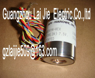
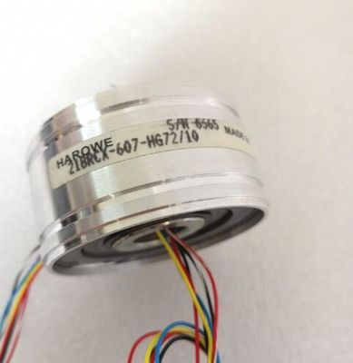
| Brand Name: | HAROWE |
| Certification: | CE |
| Model Number: | 10BRCX-401-H1/15 |
| Minimum Order Quantity: | 1pcs |
|---|---|
| Packaging Details: | carton |
| Delivery Time: | in stock |
| Payment Terms: | T/T, Western Union, MoneyGram |
| Supply Ability: | 100pcs/week |
| HAROWE: | HAROWE | 10BRCX-401-H1/15: | 10BRCX-401-H1/15 |
|---|---|---|---|
| Material: | Iron | Color: | Black |
| Temperature: | 20-90 | Wire: | Wire |
| Germany: | Germany | Dimension: | 90mm |
| Increased production availability thanks to online scan and verification of existing systems | |
| Transparency before commissioning through importing and simulation of existing STEP 7 projects |
|
| Efficiency through securing existing investments in the long term and optimal exploitation of resourcesThe module has the following technical properties: |
● 8 digital outputs, electrically isolated in groups of 4
– of which optional channels 0 and 4 are available for pulse width modulation (PWM).
● Rated output voltage 24 V DC
● Rated output current 2 A
● Configurable substitute values (per channel)
● Configurable diagnostics (per channel)
● Suitable for solenoid valves, contactors, DC contactors and indicator lights
● Switching cycle counter for connected actuators, e.g. solenoid valves
The module supports the following functions:The following table shows the compatibility of the modules and the dependencies between
hardware functional status (FS) and firmware version (FW) used:
Hardware functional
status
Firmware version Note
FS01 V1.0.0 to V2.1.0 Upgrade and downgrade possible between V1.0.0
and V2.1.0
FS02 V1.0.0 to V2.1.0 Upgrade and downgrade possible between V1.0.0
and V2.1.0
FS03 V2.2.0 Upgrade and downgrade possible between V2.2.0
and higher
Accessories
The following accessories are supplied with the module and can also be ordered separately
as spare parts:
● Labeling strips
● U connector
● Universal front cover
Other components
The following component can be ordered separately:
Front connectors, including potential jumpers and cable ties
You can find additional information on accessories in the system manual /ET Channels 0 and 4 of the module support the pulse width modulation (PWM) function. The
pulse width modulation function can be used to easily generate periodic pulses with a
constant rated voltage and a variable pulse duration for the above-mentioned channels.
Advantages
● Automatic generation of periodic signals (without user program).
● Possibility of power reduction, e.g. in solenoid valves.
Typical areas of application:
● Control of proportional valves and way values (e.g. energy saving by reducing the holding
current).
● Heating control e.g. via an external additional power unit.
Requirement
Firmware version as of V2.1.0 of the module.
Rules
Channels 0 and 4 can be used together and individually in pulse width modulation mode.
The remaining channels can continue to be used as digital outputs.
Configuration
You configure the pulse width modulation with the following parameters:
● Pulse width modulation mode for activating the function
● Pulse width modulation (time period)n the pulse width modulation mode, the two outputs (channels 0 and 4) provide one pulse
width modulated output signal.
Pulse width modulation is characterized by its time period (frequency) and its duty factor
(also referred to as ON period or Duty Cycle ). The duty factor describes the relation
between pulse duration and time period.
The pulse duration is derived from the time period and the duty factor: Pulse duration = duty
factor x time period.
Example for duty factor of 50% and time period of 10 ms:
Pulse duration 0.5 x 10 ms = 5 ms
You define the duty factor for channels 0 and 4 in the user program using the output value
(0 ... 1000) in the process image output; see section Address space operating mode pulsewidth
modulation (Page 29).
The output signal is a square wave signal (pulse sequence of on and off pulses).
① Time period T (2 to 100 ms); Frequency of the pulse width modulation: f = 1/T (10 to 500 Hz)
② Pulse duration (duty factor x time period)
Figure 2-2 How pulse width modulation works
Minimum pulse duration
The minimum pulse duration is 300 μs due to the hardware. The duty factor can be adjusted
from 0.0 to 100.0%. The time period can be adjusted from 2 to 100 ms.
Example: If you configure a time period of 2 ms and set a duty factor of 10% for the output,
this results in a pulse duration of 200 μs. In fact, the output works with a minimum pulse
duration of 300 μs.The pulse duration of the actual signal profile is slightly longer than the specified, ideal pulse
duration.
The figure below shows the reaction of the output to control by PWM. The blue line shows
the specified, ideal signal profile (square wave signal), with which the output is controlled.
The red dashed line shows the actual signal profile on the output terminal, caused by the
externally connected load.Time period
② Pulse duration (duty factor x time period)