|
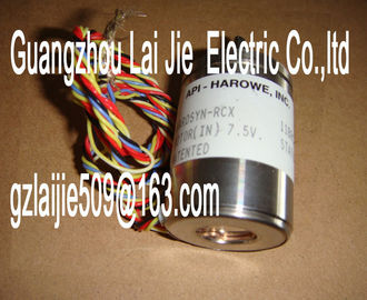
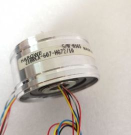
| Place of Origin: | GERMANY |
| Brand Name: | HAROWE |
| Certification: | CE |
| Model Number: | 10BRCX-401-J1A/15 |
| Minimum Order Quantity: | 1pcs |
|---|---|
| Packaging Details: | carton |
| Delivery Time: | in stock |
| Payment Terms: | T/T, Western Union, MoneyGram |
| Supply Ability: | 100pcs/week |
| HAROWE: | HAROWE | 10BRCX-401-J1A/15: | 10BRCX-401-J1A/15 |
|---|---|---|---|
| GERMANY: | GERMANY | Color: | Black |
| Temperature: | 20-90 | Wire: | Wire |
| Dimension: | 90mm | Material: | Iron |
| Figure 2-3 Pulse waveform at output terminaHigh starting current is required to activate a solenoid valve. When the solenoid valve is | |
| activated, the current requirement is lower; it only has to be held in position. This timedependent current requirement can be met well with the PWM function. |
|
| The "ValveControl" function block shown below sets the holding current required by a solenoid valve only after the configured time (HoldTime) has expired. You can generate the |
required holding current with a duty factor (PWM duty cycle << 100%). While "HoldTime" is
running, the output is set (duty factor = 100 %) to generate a high starting torque for the
solenoid valve.The function records the number of switching cycles of the output and thus the switching
cycles of a connected actuator, such as those of solenoid valves. When the specified
number of switching cycles is reached, the "Limit value warning" maintenance interrupt is
triggered, provided it is configured and enabled. When replacing the actuator, you can reset
the switching cycle counter from the user program.
When replacing modules, you have the option of pre-initializing the switching cycle counter
from the user program.
Typical areas of application:
● Recording the number of switching cycles of the connected devices, e.g. solenoid valves
or load contactors
● Predictive maintenance
Advantages
● You configure this function instead of programming.
● "Monitoring" of each individual channel is possible. You can select which outputs are
"monitored".
● You can adapt the plant configuration flexibly and individually.
● Easy to service and maintain. You can enable and disable the switching cycle counter via
the user program.
● Increase in plant availability. You can schedule actuator replacement in advance for the
next maintenance cycle.
Requirement
Firmware version as of V2.2.0 of the module.
Configuration
You configure the switching cycle counter with the following parameters:
● Switching cycle counter enabled/disabled
● Trigger maintenance interrupt when the limit is reached
● Set limit for maintenance interruptThe module counts the switching cycles by evaluating the rising edges of an output signal. If
the module detects a rising edge, the switching cycle counter (24-bit) for the respective
channel is incremented. After an overflow of the switching cycle counter, it starts again with
0.
If you activate the "Maintenance switching cycles" parameter, the "Limit warning" of the
maintenance interrupt is triggered when the limit is exceeded. Alternatively, activate the
maintenance interrupt in the parameter data sets starting at DS 64.
The current counter states are stored on the module cyclically (approx. every 20 seconds)
and retentively. The switching cycle counters are reset each time the module is restarted
(power off/on).
You activate the function with the "Switching cycle counter" parameter or in the parameter
data sets starting at DS 64.
You can read the current counter states with data set DS 129. Data set DS 129 contains the
counter status for each channel in UDINT format.
You can read the limits for each channel in UDINT format with data set DS 130.
Data set DS 131 enables you to overwrite the current counter value for each switching cycle
counter.
You can set a limit for each switching cycle counter with the "Switching cycle limit" parameter
or with data set DS 131.This section contains the block diagram of the module and outlines various wiring options.
You can find information on wiring the front connector, establishing a cable shield, etc. in the
"Wiring" section of system manual /ET 200MP The example in the following figure shows the terminal assignment and the assignment of
the channels. You can optionally assign parameters to channels 0 and channel 4 for pulse
width modulation mode. If you set the channel 0 and channel 4 for the pulse width modulation mode, then you need
to wire the outputs CH0 and CH4 with an external diode (blocking voltage UR > 60 V; letthrough
current IF > 1.5 A); see figure beloWhen you assign the module parameters in STEP 7, you use various parameters to specify
the module properties. The following table lists the configurable parameters. The effective
range of the configurable parameters depends on the type of configuration. The following
configurations are possible:
● Central operation with a CPU
● Distributed operation on PROFINET IO in an ET 200MP system
● Distributed operation on PROFIBUS DP in an ET 200MP system
For parameter assignment in the user program, the parameters are transferred to the
module using the WRREC instruction (parameter assignment in RUN) and data records; see
chapter Parameter assignment (Page 43). The table below lists the parameters in DQ mode. These parameters apply to channels 0 to
7.
Table 4- 1 Configurable parameters and their defaults If you enable diagnostics for multiple channels, you will receive an alarm surge on failure of the supply voltage because
each enabled channel will detect this fault. You can prevent this message burst by assigning the diagnostics function to
one channel only.Enabling of the diagnostics, for lacking or insufficient supply voltage L+.
Short circuit to ground
Enabling of the diagnostics if a short-circuit of the actuator supply to ground occurs.
Maintenance switching cycles
You use this parameter to enable the maintenance interrupt "Limit value warning" when the
switching cycle limit is violated.
You configure the limit with the parameter "Switching cycle limit" for each channel CHx.
Switching cycle counter
Channel-by-channel enable of switching cycle counter (Page 17).
Reaction to CPU STOP
Determines the reaction of the output when the CPU goes into the STOP state or when the
connection to the CPU is interrupted.
Switching cycle limit
Defines the limit channel-by-channel. If this value is exceeded, the "Limit value warning"
maintenance interrupt is signaled.