 |
| Place of Origin: | GERMANY |
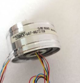
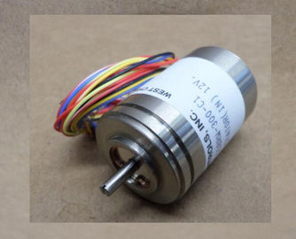
| Brand Name: | HAROWE |
| Certification: | CE |
| Model Number: | 10BRCX-401-J2/15 |
| Minimum Order Quantity: | 1pcs |
|---|---|
| Packaging Details: | carton |
| Delivery Time: | in stock |
| Payment Terms: | T/T, Western Union, MoneyGram |
| Supply Ability: | 100pcs/week |
| HAROWE: | HAROWE | 10BRCX-401-J2/15: | 10BRCX-401-J2/15 |
|---|---|---|---|
| GERMANY: | GERMANY | Temperature: | 20-90 |
| Color: | Black | Dimension: | 90mm |
| Wire: | Wire | Material: | Iron |
| Enter an integer value between 0 and 16777214. Refer to the data sheet of the connected actuator. We recommend that you do not enter this maximum value, but instead set it to 80% |
|
| or 90%, for example, so that you have enough time to replace the actuator as a preventive measure.The table below lists the parameters in pulse width modulation mode. These parameters |
|
| apply to channels 0 and 4. Table 4- 2 Configurable parameters and their defaults Enabling of the diagnostics for missing or |
insufficient supply voltage L+.
Short-circuit to ground
Enabling of the diagnostics if a short-circuit of the actuator supply to ground occurs.
Reaction to CPU STOP
Determines the reaction of the output when the CPU goes into the STOP state or when the
connection to the CPU is interrupted.
Operating mode
Specifies the operating mode in which the channels 0 and 4 of the module are operated.
● Digital output DQ as digital output channel
● Pulse width modulation, see section Pulse-width modulation (PWM) (Page 13)
Pulse width modulation time period
Specifies the period duration and therefore the frequency of the pulse width modulation.
See sectionPulse-width modulation (PWM) (Page 13) The module can be configured differently in STEP 7; see following table. Depending on the
configuration, additional/different addresses are assigned in the process image of the
outputs/inputs.
Configuration options of DQ 8x24VDC/2A HF
You can configure the module with STEP 7 (TIA Portal) or with a GSD file.
When you configure the module by means of the GSD file, the configurations are available
under different abbreviations/module names.
The following configurations are possible:The value status is always activated for the following module names:
● DQ 8x24VDC/2A HF QI
● DQ 8x24VDC/2A HF MSO
● DQ 8x24VDC/2A HF PWM
An additional bit is assigned to each channel for the value status. The bit for the value status
indicates if the output value specified by the user program is actually pending at the module
terminal (0 = value is incorrect).
Note
The maintenance interrupt "Limit value warning" has no effect on the value status.The following figure shows the assignment of the address space for the configuration as a 8-
channel module with value status. You can freely assign the start address for the module.
The addresses of the channels are derived from the start address.
The letter "a" is are printed on the module; "AB a" stands for module start address output
byte a.
For the configuration as a 1 x 8-channel module (module-internal Shared Output, MSO),
channels 0 to 7 of the module are copied to multiple submodules. Channels 0 to 7 are then
available with identical values in various submodules. These submodules can be assigned to
up to four IO controllers when the module is used in a shared device:
● The IO controller to which submodule 1 is assigned has write access to outputs 0 to 7.
● The IO controllers to which submodule 2, 3, or 4 is assigned have read access to outputs
0 to 7.
The number of usable IO controllers depends on the interface module used. Observe the
information in the manual for the particular interface module.
Value status (Quality Information, QI)
The meaning of the value status depends on the submodule on which it occurs.
For the first submodule (=basic submodule), the value status 0 indicates that the value is
incorrect or that the IO controller of the basic submodule is in STOP state.
For 2nd to 4th submodule (=MSO submodule), the value status 0 indicates that the value is
incorrect or one of the following errors has occurred:
● The basic submodule is not yet configured (not ready).
● The connection between the IO controller and the basic submodule has been interrupted.
● The IO controller of the basic submodule is in STOP or POWER OFF state.You can find information on the Shared Input/Output (MSI/MSO) function in the section
Module-Internal Shared Input/Output (MSI/MSO) of the PROFINET with STEP 7 V13 If you use the module in the "Pulse width modulation mode" (channels 0 and 4), the module
uses the following address spaces:
● 6 bytes in the process image output
● 1 byte in the process image input
Allocation of the process image
If you have set "Pulse width modulation" mode for channels 0 and 4 in the parameter, bits 0
and 4 have no significance. Enter the on-load factor (duty factor) in the following output
bytes; see the figure belowThe following table explains the meaning of the status and error displays. Remedial
measures for diagnostic alarms can be found in section Diagnostic alarms (Page 33).
RUN and ERROR LED
Table 5- 1 Status and error displays RUN and ERROR
LED Meaning Solution
RUN ERROR
Off Off
Voltage missing or too low at backplane bus. ? Switch on the CPU and/or the system power
supply modules.
? Verify that the U connectors are inserted.
? Check to see if too many modules are inserted.
Flashes Off
The module starts and flashes until the valid
parameter assignment is set.
---
On Off
Module is configured.