 |
| Place of Origin: | GERMANY |
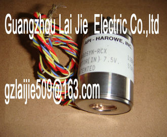
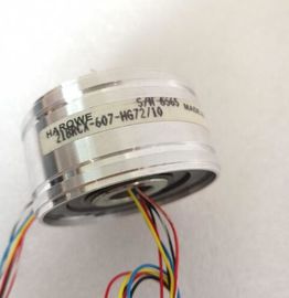
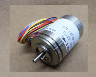
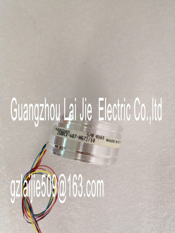
| Brand Name: | HAROWE |
| Certification: | CE |
| Model Number: | 10BRCX-401-P1 |
| Minimum Order Quantity: | 1pcs |
|---|---|
| Packaging Details: | carton |
| Delivery Time: | in stock |
| Payment Terms: | T/T, Western Union, MoneyGram |
| Supply Ability: | 100pcs/week |
| HAROWE: | HAROWE | Material: | Iron |
|---|---|---|---|
| Temperature: | 20-90 | Dimension: | 90mm |
| Germany: | Germany | Color: | Black |
| Wire: | Wire |
| On Flashes Indicates module errors (at least one error at |
|
| one channel, e.g., short-circuit to ground). Evaluate the diagnostics data and eliminate the |
|
| error (e.g., check the cables). Flashes Flashes |
Hardware defective. Replace the moduleupply voltage L+ too low or missing. Check supply voltage L+.
On
Supply voltage L+ is present and OK.0 = Status of the output signal. ---
On
1 = Status of the output signal. ---
On
Channel parameters assigned (channel fault
pending; a short-circuit to ground is pending at
the respective channel).
Check the wiring and remedy the short-circuit
to ground.
Supply voltage L+ too low or missing. Check supply voltage L+.
5.2 Interrupts
The digital output module DQ 8x24VDC/2A HF supports diagnostic interrupts and
maintenance interrupts.
You can find detailed information on the error event in the error organization block with the
"RALRM" instruction (read additional interrupt info) and in the STEP 7 online help.
Diagnostic interrupt
The module generates a diagnostic interrupt at the following events:
● No supply voltage L+
● Short circuit to ground
● Parameter assignment error
Maintenance interrupt
The module generates a maintenance interrupt at the following events:
● Limit value warninghe module. The diagnostics alarms can be read out in the diagnostics buffer of the CPU, for
example. You can evaluate the error codes with the user program.
If the module is operated distributed with PROFIBUS DP in an ET 200MP system, you have
the option to read out diagnostics data with the instruction RDREC or RD_REC using data
record 0 and 1. The structure of the data records is available on the in the "Manual
for interface module IM 155-5 DP ST (6E155-5BA00-0AB0)".Short-circuit or overload at the channel
Check the wiring/actuator. Check
the ambient temperature.
Parameter assignment
error
10H ? The module cannot evaluate parameters
for the channel
? Incorrect parameter assignment
Correct the parameter assignment
Load voltage missing 11H Supply voltage L+ of the module is
missing
Connect supply voltage L+ to module/channel
Limit value warning 17H The configured limit for switching
cycles has been exceeded.
? Replace actuator as a precautionary
measure
? Reset counter with DS131
* This diagnostic message can be output with pulse duration <500 microseconds in pulse width modulation mode. DisabThe following table shows the technical specifications as of 06/2018. You will find a data
sheet including daily updated technical specifications on the Product type designation DQ 8x24VDC/2A HF
HW functional status FS03
Firmware version V2.2.0
? FW update possible Yes
Product function
? I&M data Yes; I&M0 to I&M3
Engineering with
? STEP 7 TIA Portal configurable/integrated
as of version
V13 SP1 / -
? STEP 7 configurable/integrated as of version
V5.5 SP3 / -
? PROFIBUS as of GSD version/GSD revision
V1.0 / V5.1
? PROFINET as of GSD version/GSD revision
V2.3 / -
Operating mode
? DQ Yes
? DQ with energy-saving function Yes; with an application
? PWM Yes
? Cam control (switching at comparison values)
No
? Oversampling No
? MSO Yes
? Integrated operating cycle counter Yes
Technical specifications
DQ 8x24VDC/2A HF Digital Output Module (6E522-1BF00-0AB0)
Manual, 06/2018, A5E03485650-AF 35
Article number 6E522-1BF00-0AB0
Supply voltage
Rated value (DC) 24 V
permissible range, lower limit (DC) 20.4 V
permissible range, upper limit (DC) 28.8 V
Reverse polarity protection Yes; through internal protection with 10 A per
group
Input current
Current consumption, max. 40 mA; 20 mA Type of digital output Transistor
Number of digital outputs 8
Current-sourcing Yes
Short-circuit protection Yes
? Response threshold, typ. 3 A
Limitation of inductive shutdown voltage to -17 V
Controlling a digital input Yes
Digital output functions, parameterizable
? Freely usable digital output Yes
? PWM output Yes
– Number, max. 2
– Cycle duration, parameterizable Yes; 2 ... 100 ms continuous
– ON period, min. 0 %
– ON period, max. 100 %
– Resolution of the duty cycle 0.1 %
– Minimum pulse duration 300 μs
Switching capacity of the outputs
? on lamp load, max. 10 W
Load resistance range
? lower limit 12 ?
? upper limit 4 k?
Output voltage
? for signal "1", min. L+ (-0.8 V)? for signal "1" rated value 2 A
? for signal "1" permissible range, max. 2.4 A; Note derating specification for PWM operation
? for signal "0" residual current, max. 0.5 mA
Output delay with resistive load
? "0" to "1", typ. 80 μs
? "0" to "1", max. 100 μs
? "1" to "0", typ. 300 μs
? "1" to "0", max. 500 μs
Parallel switching of two outputs
? for logic links Yes
? for uprating No