|
| Place of Origin: | GERMANY |
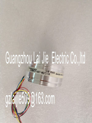
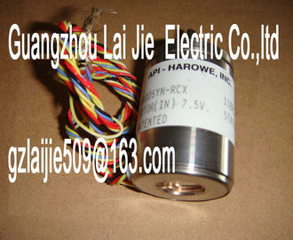
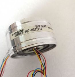
| Brand Name: | HAROWE |
| Certification: | CE |
| Model Number: | 10BRCX-500-A9/15 |
| Minimum Order Quantity: | 1pcs |
|---|---|
| Packaging Details: | carton |
| Delivery Time: | in stock |
| Payment Terms: | T/T, Western Union, MoneyGram |
| Supply Ability: | 100pcs/week |
| HAROWE: | HAROWE | 10BRCX-500-A9/15: | 10BRCX-500-A9/15 |
|---|---|---|---|
| GERMANY: | GERMANY | Temperature: | 20-90 |
| Dimension: | 90mm | Color: | Black |
| Wire: | Wire | Material: | Iron |
| for redundant control of a load Yes Switching frequency |
|
| with resistive load, max. 100 Hz; With PWM operation: 500 Hz ? with inductive load, max. 0.5 Hz; According to IEC 60947-5-1, DC-13; ma |
|
| 500 Hz with PWM operation only with external circuit; see additional description in the manual |
on lamp load, max. 10 Hz
Total current of the outputs
? Current per channel, max. 2 A; see additional description in the manual
? Current per group, max. 8 A; see additional description in the manual
? Current per module, max. 16 A; see additional description in the manual
Cable length
? shielded, max. 1 000 m
? unshielded, max. 600 m
Isochronous mode
Isochronous operation (application synchronized
up to terminal)
No
Interrupts/diagnostics/status information
Diagnostics function Yes
Substitute values connectable Yes
Alarms
? Diagnostic alarm Yes Monitoring the supply voltage Yes
? Wire-break No
? Short-circuit Yes
? Group error Yes
Diagnostics indication LED
? RUN LED Yes; Green LED
? ERROR LED Yes; Red LED
? MAINT LED Yes; yellow LED
? Monitoring of the supply voltage (PWRLED)
Yes; Green LED
? Channel status display Yes; Green LED
? for channel diagnostics Yes; Red LED
? for module diagnostics Yes; Red LED
Potential separation
Potential separation channels
? between the channels No
? between the channels, in groups of 4
? between the channels and backplane bus Yes
Isolation
Isolation tested with 707 V DC (type test)
Standards, approvals, certificates
Suitable for safety-related tripping of standard
modules
Yes; From FS03
Highest safety class achievable for safety-related
tripping of standard modules
? Performance level according to ISO 13849-
1
PL d
? Category according to ISO 13849-1 Cat. 3
? SILCL according to IEC 62061 SILCL 2
Decentralized operation
Prioritized startup Yes
Dimensions
Width 35 mm
Height 147 mm
Depth 129 mm
Weights
Weight, approx. 240 gThe following graphs show the loading capacity of the outputs in relation to the mounting
The dimensional drawing of the module on the mounting rail, as well as a dimensional
drawing with open front cover, are provided in the appendix. Always observe the specified
dimensions for installations in cabinets, control rooms, etc.When a GSD file is used to configure a module, dependencies can arise when "assigning the
parameters".
There are no dependencies for this module. You can assign the individual parameters in any
combination.
Parameter assignment in the user program
You have the option to reconfigure the module in RUN (e.g. the response of selected
channels to the CPU-STOP state can be changed in RUN without having an effect on the
other channels).
Parameter assignment in RUN
The WRREC instruction is used to transfer the parameters to the module using data sets 64
to 71. The parameters set in STEP 7 do not change in the CPU, which means the
parameters set in STEP 7 are still valid after a restart.
The parameters are only checked for plausibility by the module after the transfer.
Output parameter STATUS
The module ignores errors that occurred during the transfer of parameters with the WRREC
instruction and continues operation with the previous parameter assignment. However, a
corresponding error code is written to the STATUS output parameter.
The description of the WRREC instruction and the error codes is available in the STEP 7
online help.The channel parameters of the module are included in data sets 64 to 71 and are assigned
as follows:
● Data set 64 for channel 0 (PWM operating mode possible)
● Data record 65 for channel 1
● Data set 66 for channel 2
● Data set 67 for channel 3
● Data set 68 for channel 4 (PWM operating mode possible)
● Data set 69 for channel 5