 |
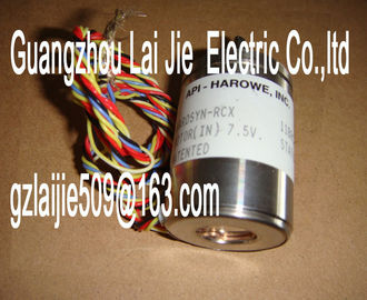
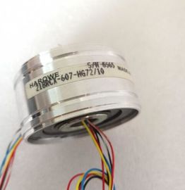
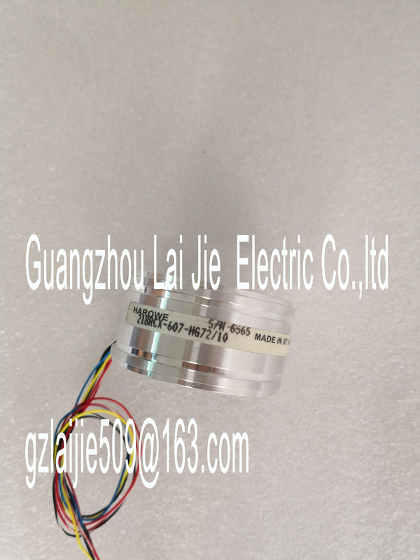
| Place of Origin: | GERMANY |
| Brand Name: | HAROWE |
| Certification: | CE |
| Model Number: | 11BRCT300M10A |
| Minimum Order Quantity: | 1pcs |
|---|---|
| Packaging Details: | carton |
| Delivery Time: | in stock |
| Payment Terms: | T/T, Western Union, MoneyGram |
| Supply Ability: | 100pcs/week |
| HAROWE: | HAROWE | 11BRCT300M10A: | 11BRCT300M10A |
|---|---|---|---|
| GERMANY: | GERMANY | TEMPERATURE: | TEMPERATURE |
| Material: | Iron | Color: | Black |
| Dimension: | 90mm |
| Wiring section of the system manual /ET 200MPYou can find additional information on compensating the reference junction temperature in | |
| the function manual Analog value processing record in the section Structure of a data record for dynamic reference temperature | |
| ote • You may use and combine the different wiring options for all channels. |
Do not insert the potential jumpers supplied with the front connectorMeaning of the abbreviations used in the following figures:
Un+/Un- Voltage input channel n (voltage only)
Mn+/Mn- Measuring input channel n
In+/In- Current input channel n (current only)
Ic n+/Ic n- Current output for RTD, channel n
UVn Supply voltage at channel n for 2-wire transmitters (2WMT)
Comp+/Comp- Compensation input
IComp+/IComp- Current output for compensation
L+ Connection for supply voltage
M Ground connection
MANA Reference potential of the analog circuitt for the power supply element
The power supply element is plugged onto the front connector for powering the analog
module. Wire the supply voltage to terminals 41 (L+) and 44 (M). You can use terminals 42
(L+) and 43 (M) to loop the potential to the next module.① Analog-to-digital converter (ADC) CHx Channel or 9 x channel status (green/red)
② Backplane bus interface RUN Status display LED (green)
③ Supply voltage via power supply element ERROR Error display LED (red)
④ Equipotential bonding cable (optional) PWR LED for power supply (green)The example in the following figure shows the pin assignment for current measurement with
4-wire transmitters.Wiring 4-wire transmitter CHx Channel or 9 x channel status (green/red)
② Analog-to-digital converter (ADC) RUN Status display LED (green)
③ Backplane bus interface ERROR Error display LED (red)
④ Supply voltage via power supply element PWR LED for power supply (green)
⑤ Equipotential bonding cable (optional)
Figure 3-3 Block diagram and pin assignment for current measurementThe example in the following figure shows the pin assignment for current measurement with
2-wire transmitters.Wiring 2-wire transmitter CHx Channel or 9 x channel status (green/red)
② Analog-to-digital converter (ADC) RUN Status display LED (green)
③ Backplane bus interface ERROR Error display LED (red)
④ Supply voltage via power supply element PWR LED for power supply (green)
⑤ Equipotential bonding cable (optional)
Figure 3-4 Block diagram and pin assignment for current measurementThe example in the following figure shows the pin assignment for 2-, 3- and 4-wire
connections of resistance-based sensors or thermal resistors.4-wire connection CHx Channel or 9 x channel status (green/red)
② 3-wire connection RUN Status display LED (green)
③ 2-wire connection ERROR Error display LED (red)
④ Analog-to-digital converter (ADC) PWR LED for power supply (green)
⑤ Backplane bus interface
⑥ Supply voltage via power supply element
⑦ Equipotential bonding cable (optional)
Figure 3-5 Block diagram and pin assignment for 2-, 3- and 4-wire connectionsThe following figure shows an example of the pin assignment for grounded thermocouples
for internal compensation.① Wiring of a thermocouple (grounded) for internal compensation
CHx Channel or 9 x channel status (green/red)
② Analog-to-digital converter (ADC) RUN Status display LED (green)
③ Backplane bus interface ERROR Error display LED (red)
④ Supply voltage via power supply element PWR LED for power supply (green)
⑤ Equipotential bonding cable (optional)
Figure 3-7 Block diagram and pin assignment for grounded thermocouplesThe module is set to voltage measurement type with measuring range ±10 V by default. You
need to reassign the module parameters with STEP 7 if you want to use a different
measurement type or range.
Deactivate the input if it is not going to be used. The module cycle time is shortened and the
interference factors that lead to failure of the module (for example, triggering a hardware
interrupt) are avoided.
The following table shows the measurement types and the respective measuring range.
Table 4- 1 Measurement types and measuring rangesSee Representation of analog values
in the current measuring ranges
(Page 71) Current 4WMT
(4-wire transmitter)
0 mA to 20 mA
4 mA to 20 mA
±20 mA
Resistor
(2-wire connection) PTC
See Representation of the analog
values of resistance-based sensors/resistance
thermometers
(Page 72) Thermal resistor RTD
(3-wire connection)
(4-wire connection)
PT100 Standard/Climate
PT200 Standard/Climate
PT500 Standard/Climate
PT1000 Standard/Climate
Ni100 Standard/Climate
Ni1000 Standard/Climate
LG-Ni1000 Standard/Climatic
Thermocouple (TC) Type B