|
| Place of Origin: | GERMANY |
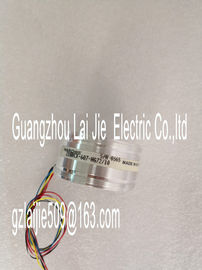
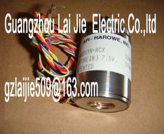
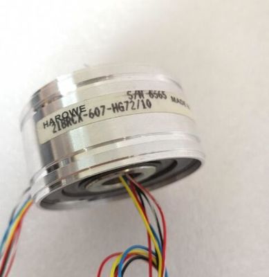
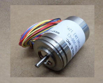
| Brand Name: | HAROWE |
| Certification: | CE |
| Model Number: | 11BRCT-300-M-10A |
| Minimum Order Quantity: | 1pcs |
|---|---|
| Packaging Details: | carton |
| Delivery Time: | in stock |
| Payment Terms: | T/T, Western Union, MoneyGram |
| Supply Ability: | 100pcs/week |
| HAROWE: | HAROWE | 11BRCT-300-M-10A: | 11BRCT-300-M-10A |
|---|---|---|---|
| GERMANY: | GERMANY | Material: | Iron |
| Temperature: | 20-90 | Color: | Black |
| Dimension: | 90mm | Wire: | Wire |
| of the organization block. The diagram below shows the assignment to the bits of double word 8 in local data.If the two high limits 1 and 2 are reached at the same time, the module always |
|
| of the organization block. The diagram below shows the assignment to the bits of double word 8 in local data.If the two high limits 1 and 2 are reached at the same time, the module always |
|
| for high limit 2. The module has the same reaction when the low limits are reached at the same time. If the |
two low limits 1 and 2 are reached at the same time, the module always signals the
hardware interrupt for low limit 1 first. After processing the hardware interrupt for low limit 1,
the module triggers the hardware interrupt for low limit 2Table 5- 4 Structure of USI = W#16#0001
Data block name Contents Remark Bytes
USI
(User Structure Identifier)
W#16#0001 Additional interrupt info for hardware interrupts
of the I/O module
2
The channel that triggered the hardware interrupt follows.
Channel B#16#00 to B#16#n Number of the event-triggering channel (n =
number of module channels -1)
1
The event that triggered the hardware interrupt follows.
Event B#16#03 Low limit violated 1 1
B#16#04 High limit violated 1
B#16#05 Low limit violated 2
B#16#06 Violation of high limit 2A diagnostics alarm is generated and the ERROR LED flashes on the module for each
diagnostics event. The diagnostics alarms can be read out in the diagnostics buffer of the
CPU, for example. You can evaluate the error codes with the user program.
If the module is operated distributed with PROFIBUS DP in an ET 200MP system, you have
the option to read out diagnostics data with the instruction RDREC or RD_REC using data
record 0 and 1. The structure of the data records is available on the in the "Manual
for interface module IM 155-5 DP ST (6ES7155-5BA00-0AB0)".mpedance of encoder circuit too high Use a different encoder type or modify the
wiring, for example, using cables with
larger cross-section
Wire break between the module and sensor
Connect the cable
Channel not connected (open) • Disable diagnostics
• Connect the channel
Overflow 7H Measuring range violated Check the measuring range
Underflow 8H Measuring range violated Check the measuring range
Parameter assignment
error
10H • The module cannot evaluate parameters
for the channel
• Incorrect parameter assignment
Correct the parameter assignment
Load voltage missing 11H Supply voltage L+ of the module is missing Connect supply voltage L+ to module/channel
Reference channel
error
15H Invalid reference temperature for the used
TC channel with compensation
Check the resistance thermometer. For
the compensation with data record, restore
communication to the module/station.
Common mode error 118H Valid common mode voltage exceeded
Causes when a 2WT is connected, e.g.:
• Wire break
• Galvanic connection to MANA
Check the wiring, e.g. sensor ground
connections, use equipotential cables
s with value status (QI)
If you configure the module with value status (QI), the module always checks all errors even
if the respective diagnostics is not enabled. But the module cancels the inspection as soon
as it detects the first error, regardless if the respective diagnostics has been enabled or not.
The result may be that enabled diagnostics may not be displayed.
Example: You have enabled "Underflow" diagnostics, but the module detects the "Wire
break" diagnostics first and aborts after this error message. The "Underflow" diagnostics is
not detected.
Recommendation: To ensure that all errors can be diagnosed reliably, select all check b